Method for manufacturing non-seamed stone corners for veneer stone surfaces

a technology of veneer stone and non-seamed stone, which is applied in the field of stone masonry, can solve the problems of unsightly joints of thin stone on the outside corners of walls, expensive buying of building stone, and inconvenient manufacturing of thin ston

Inactive Publication Date: 2005-09-20
HOLMES MARK J
View PDF5 Cites 13 Cited by
  • Summary
  • Abstract
  • Description
  • Claims
  • Application Information

AI Technical Summary

Benefits of technology

[0013]It is therefore an object of the present invention to provide a way of constructing outside corner stones for veneer stone surfaces which hide the seams which appear when thin stone veneer is used at the corners.

Problems solved by technology

However, thin stone leaves an unsightly joint on the outside corners of the wall, house, building or whatever is being laid.
The difficulty is with the external corner.
There are two inadequate solutions in the prior art.
The down side of building stone is it's expensive to buy, hard and expensive to lay, and heavy and expensive to transport.
The drawbacks to this solution are as follows: culture stone costs as much per square foot of surface area as thick building stone.
Culture stone can't be cleaned with commercial acid based masonry cleaners to remove mortar stains, as this would corrode the “stone” appearance and void the warranty.
Furthermore, culture stone doesn't lend itself to fit and finish as well as thin stone.
Culture stone trimmed up exposes the unsightly inside of the piece since the stone look of the piece is provided by a thin coating.
It is to be noted that another potential solution is not workable.
Culture stone corners cannot be used with thin stone walls because the texture of the culture stone cladding is noticeably different from thin stone, and makes the corners unsightly on that account.

Method used


Image

  • Method for manufacturing non-seamed stone corners for veneer stone surfaces
  • Method for manufacturing non-seamed stone corners for veneer stone surfaces
  • Method for manufacturing non-seamed stone corners for veneer stone surfaces

Examples


Embodiment Construction

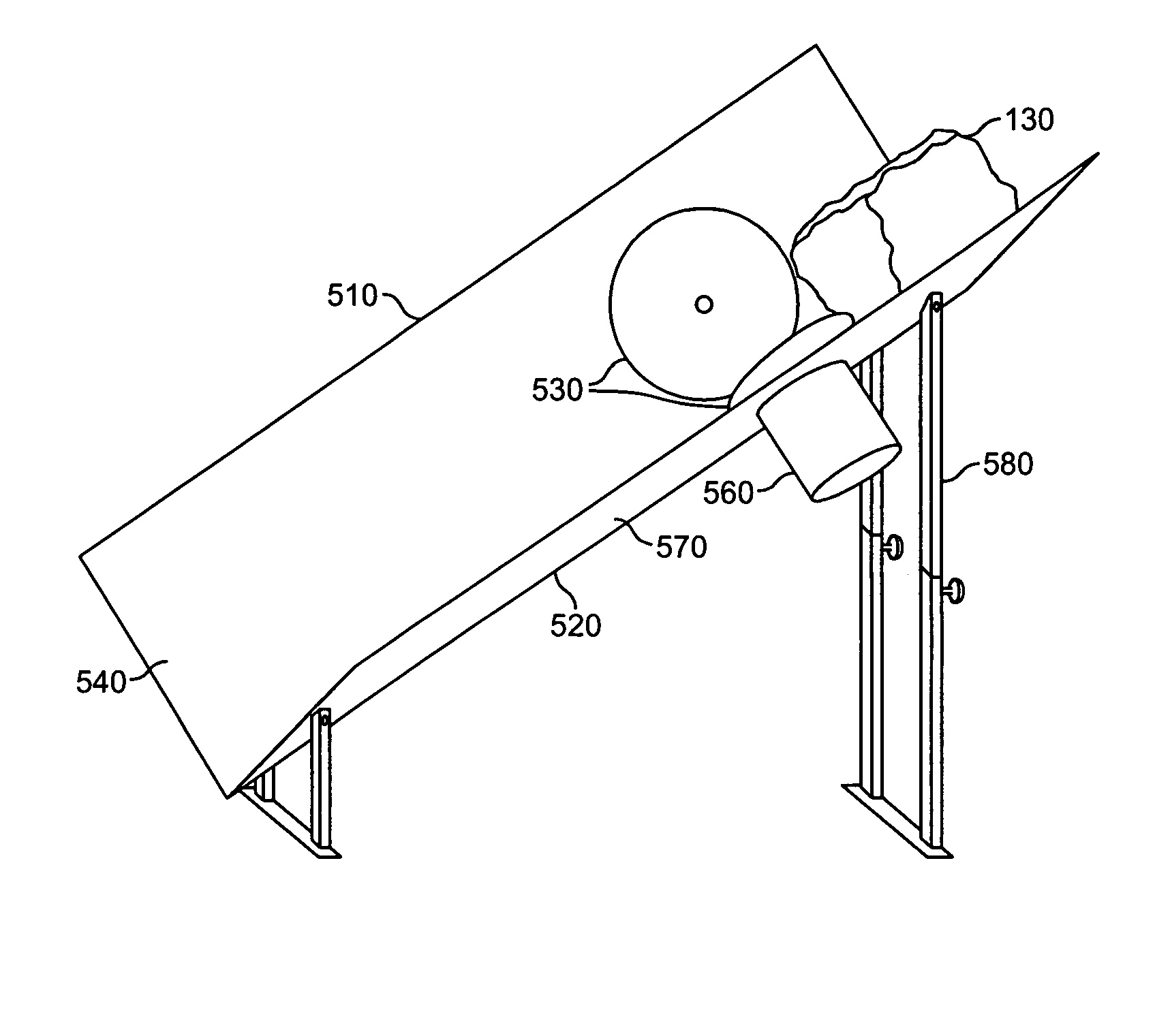
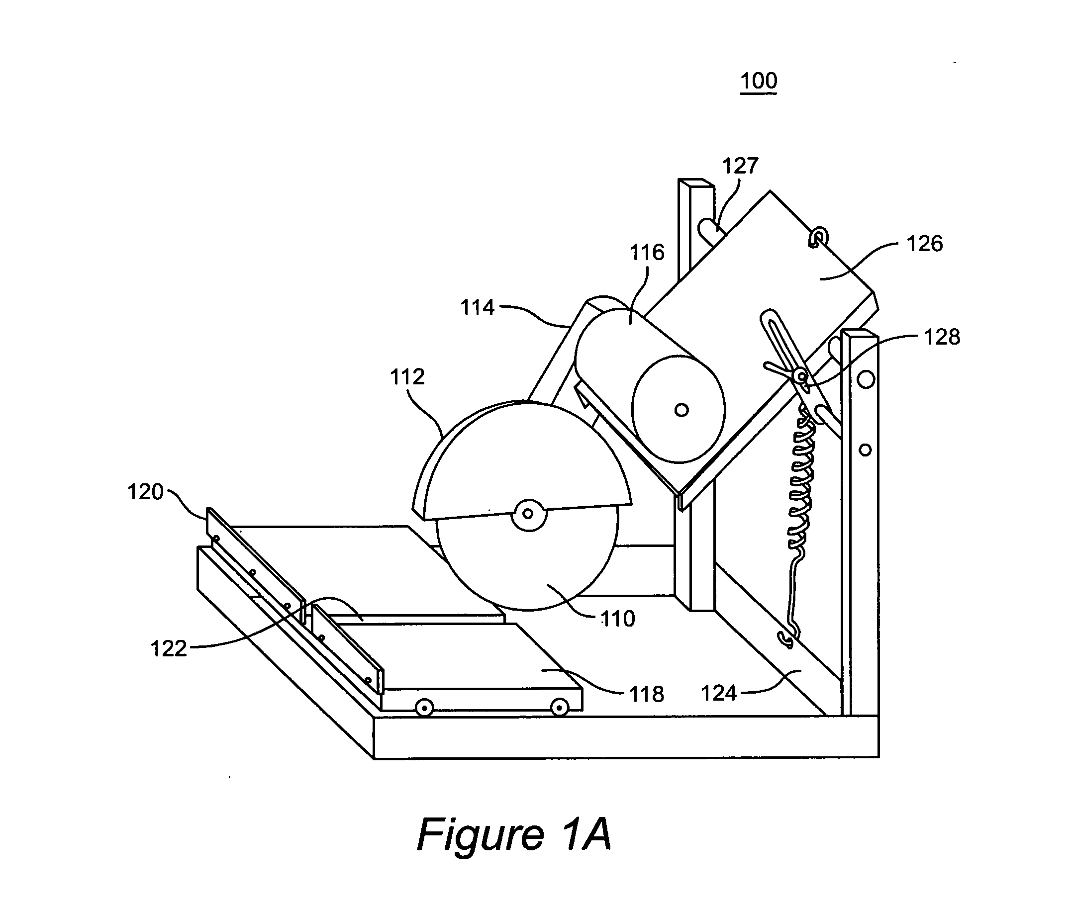
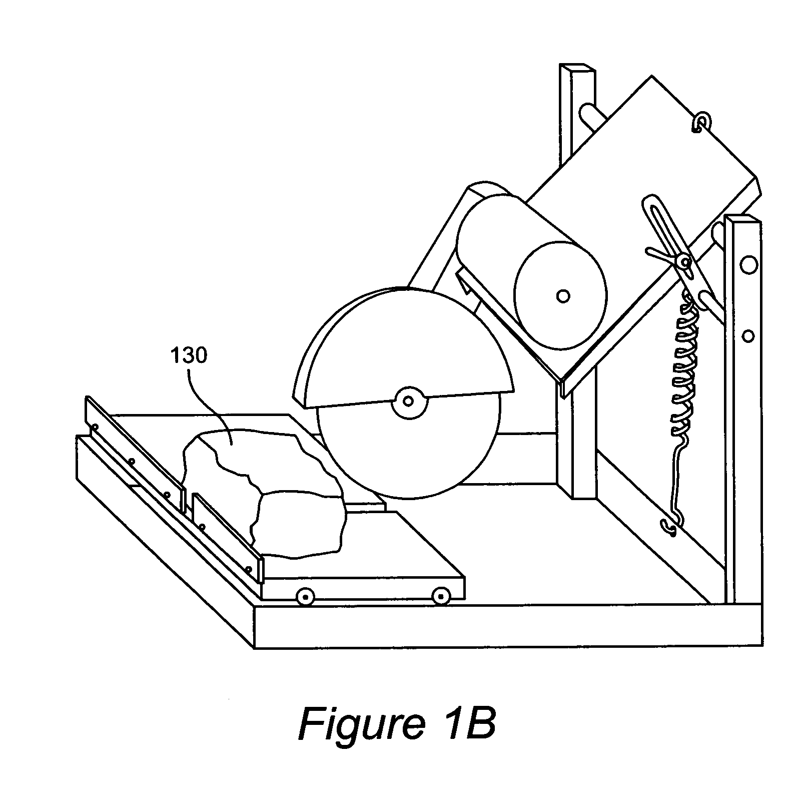
[0026]Stone corners in accordance with the invention can be made with two types of common masonry saws. The stationary saw 100 as shown in FIG. 1A can cut either wet or dry. Stone can also be cut with a hand held saw (not shown). Utilizing recent breakthroughs in stone saw blade technology, the stationary saw is the easier, safer and faster saw for implementing the invention. As shown in FIG. 1A, the stationary saw assembly includes a motor 116 connected by a drive arm 114 to saw blade 110, which is protected by a saw blade safety cover 112. The saw blade 110 is adjusted to a desired vertical height by rotating platform 126 about axis 127 and tightening adjustable brace 128. The saw blade 110 remains stationary during the cutting process. A workpiece (shown as item 130 in FIG. 1B) is placed on table 118 abutting front stop 120. Table 118 has a groove 122 to allow cutting through a workpiece.

[0027]Now turning to FIG. 1C, using a typical 14 inch saw blade machine (stationary saw assem...


PUM

PropertyMeasurementUnit
depthaaaaaaaaaa
depthaaaaaaaaaa
depthaaaaaaaaaa

Abstract

A method is disclosed for constructing non-seamed stone corners for use on outside edges formed by joining thin stone walls at right angles. Thin stone is used to lay the field of the walls. Then a building stone is oriented and fed down a chute, having perpendicular sides, through two stone cutting saws at right angles to one another, where the distance between the saw blades and the sides of the chute correspond to the thickness of the respective thin stone walls, and where the cutting edges of the saw blades have a clearance between them of about one-eighth of an inch. A residual piece is removed from the cut building stone, leaving a corner stone. These corner stones are laid on the corner formed by the right angle joint between the walls, giving the illusion of a thick building stone wall with nearly the low cost and easy laying of thin stone. Where the residual piece is large enough, it is used to cut a second corner stone in the same manner.

Description

[0001]This application is a continuation in part from application Ser. No. 10 / 195,435 filed Jul. 16, 2002 now U.S. Pat. No. 6,659,099 of the same title.BACKGROUND OF THE INVENTION[0002]1. Field of the Invention[0003]The present invention generally relates to stone masonry, and in particular to the construction of stone surfaces and corners using veneer stone.[0004]2. Background Description[0005]Formerly stone is laid as a structural component or as an aesthetic cladding or veneer on houses, buildings, walls, chimneys and as paving or flooring.[0006]Stone comes in different types: thin stone one-half inch to three inches thick that is either a field stone or is quarried and split to the appropriate size; and building stone, which is a three inch to nine inch thick stone that is either a field stone or is quarried and split to the appropriate size. Thin stone and building stone are generally the same stone except for their different thicknesses.[0007]There are many other types of ston...

Claims


Application Information

Patent Timeline
Patent Type & Authority Patents(United States)
IPC IPC(8): B24C1/04B24C1/00B28D1/04E04B5/04E04C2/04
CPCB23D45/146B23D47/045B28D1/046B28D1/047B28D1/048B28D7/04
Inventor HOLMES, MARK J
Owner HOLMES MARK J
Why Eureka
Try Eureka