

Stackable cover for container
- Summary
- Abstract
- Description
- Claims
- Application Information
AI Technical Summary
Benefits of technology
Problems solved by technology
Method used
Image

Examples
Embodiment Construction
[0019]In order to make the objective, construction, feature, and function of the present invention be more comprehensible, the present invention is described below in detail through embodiments.
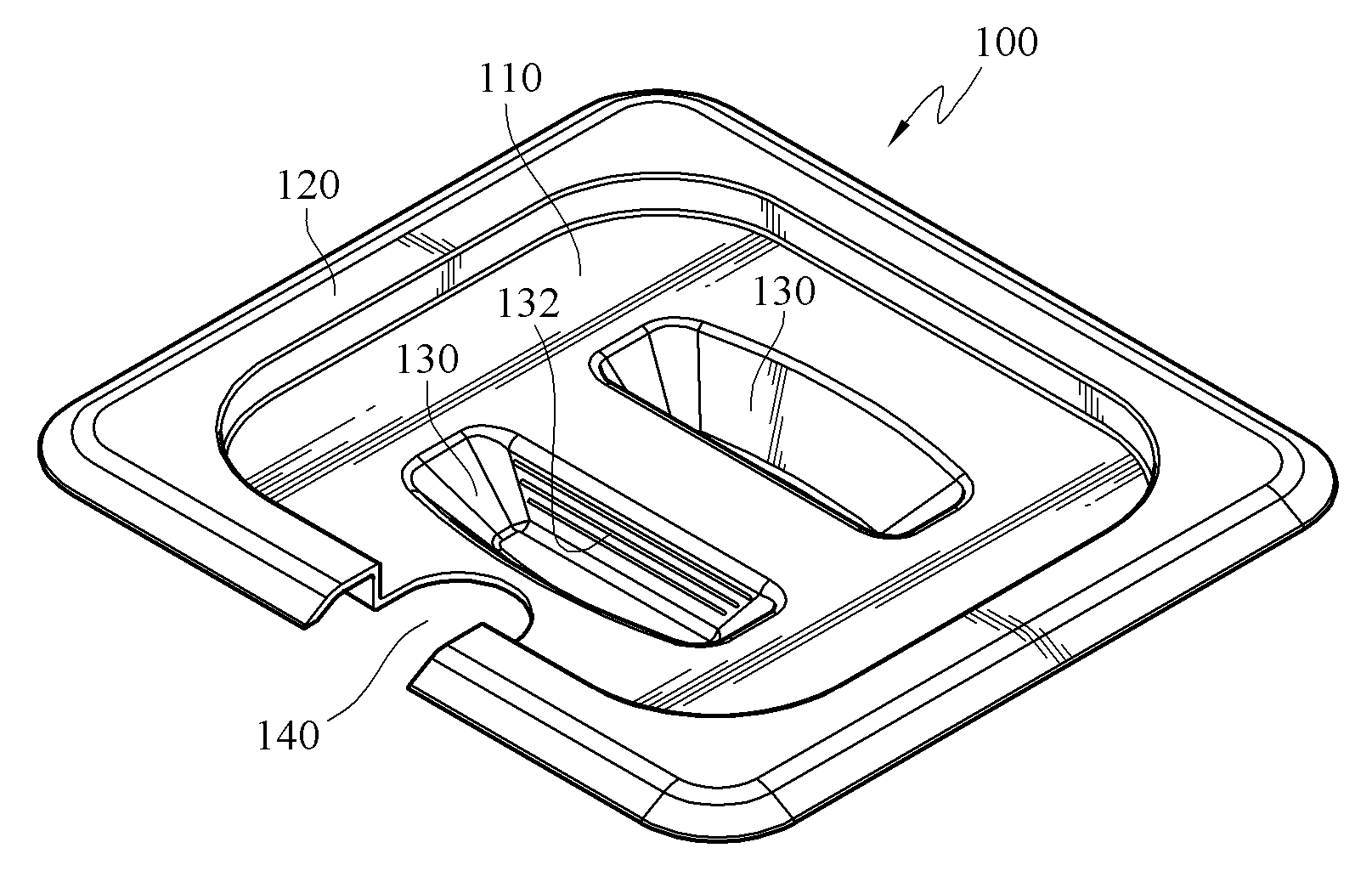
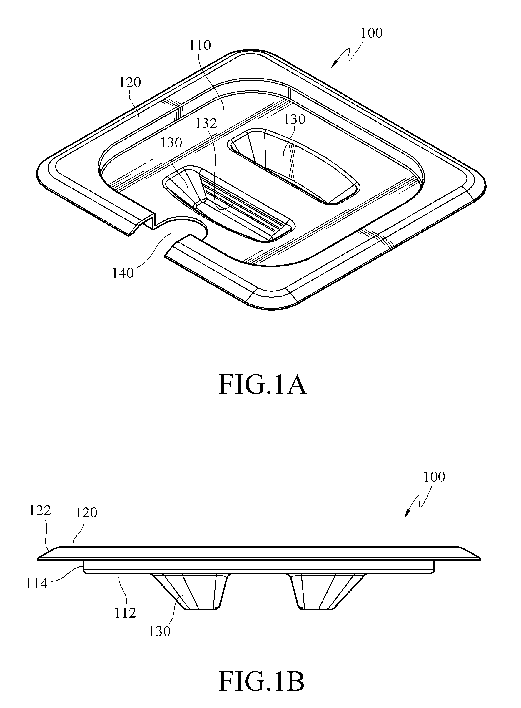
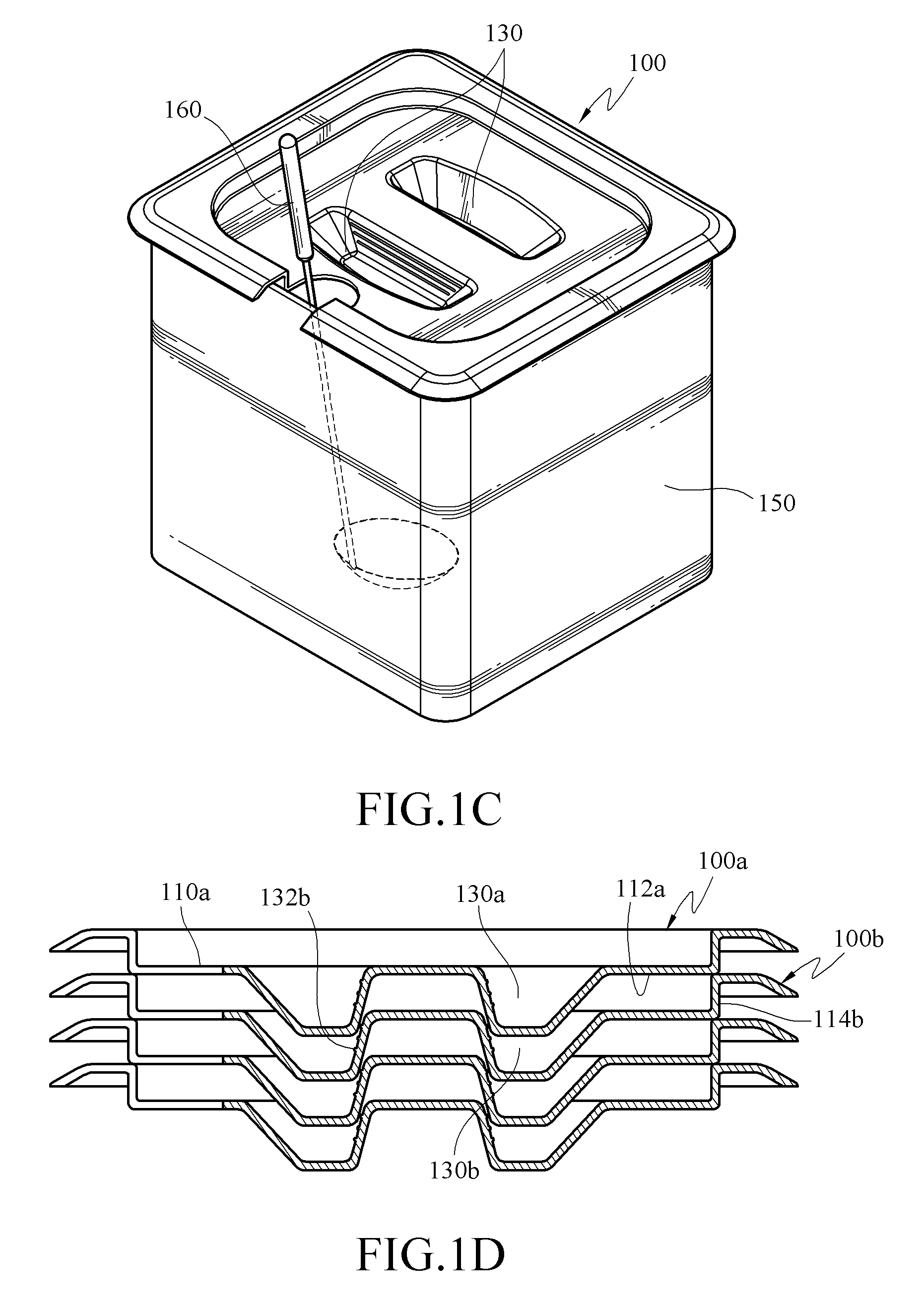
[0020]Referring to FIGS. 1A, 1B, and 1C, a stackable cover 100 of a first embodiment of the present invention is used to cover a container 150, such as pot, boiler, or steam pan, for cooking and boiling food. Although the container 150 of the present invention takes a cooking pot as an example, the stackable cover 100 of the present invention is not limited to being applied on the cooking pot. The stackable cover 100 of the first embodiment of the present invention includes a central portion 110, a peripheral portion 120, two recesses 130, and an opening 140. The stackable cover 100 is monolithically formed, for example, through die casting process or stamping.
[0021]Referring to FIGS. 1A, 1B, and 1C, the peripheral portion 120 is formed around the central portion 110 for contacting and coveri...
PUM
 Abstract
Description
Claims
Application Information