Distribution automation terminal equipment

A technology of power distribution automation and terminal equipment, which is applied in the direction of electrical components, supervision desks/panels, etc., can solve the problems that terminals are susceptible to interference, and achieve the effect of preventing transitional decline and fast and convenient storage

Active Publication Date: 2021-09-17
GUIZHOU POWER GRID CO LTD
View PDF11 Cites 0 Cited by
  • Summary
  • Abstract
  • Description
  • Claims
  • Application Information

AI Technical Summary

Problems solved by technology

[0006] Therefore, the technical problem to be solved by the present invention is to overcome the defect that terminals in the pr

Method used


Image

  • Distribution automation terminal equipment
  • Distribution automation terminal equipment
  • Distribution automation terminal equipment

Examples


Embodiment 1

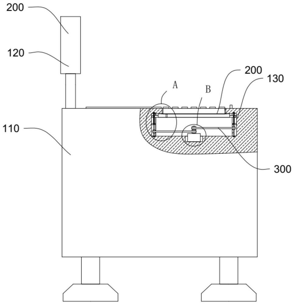
[0026] This embodiment provides a power distribution automation terminal equipment, its structure is as follows Figure 1 to Figure 6 As shown, it includes a body assembly 100, a terminal body 110, a display screen 120 and a cavity 130, the display screen 120, the display screen 120 is fixedly installed on the top of the terminal body 110; the cavity 130, the cavity 130 is opened on the terminal body 110;

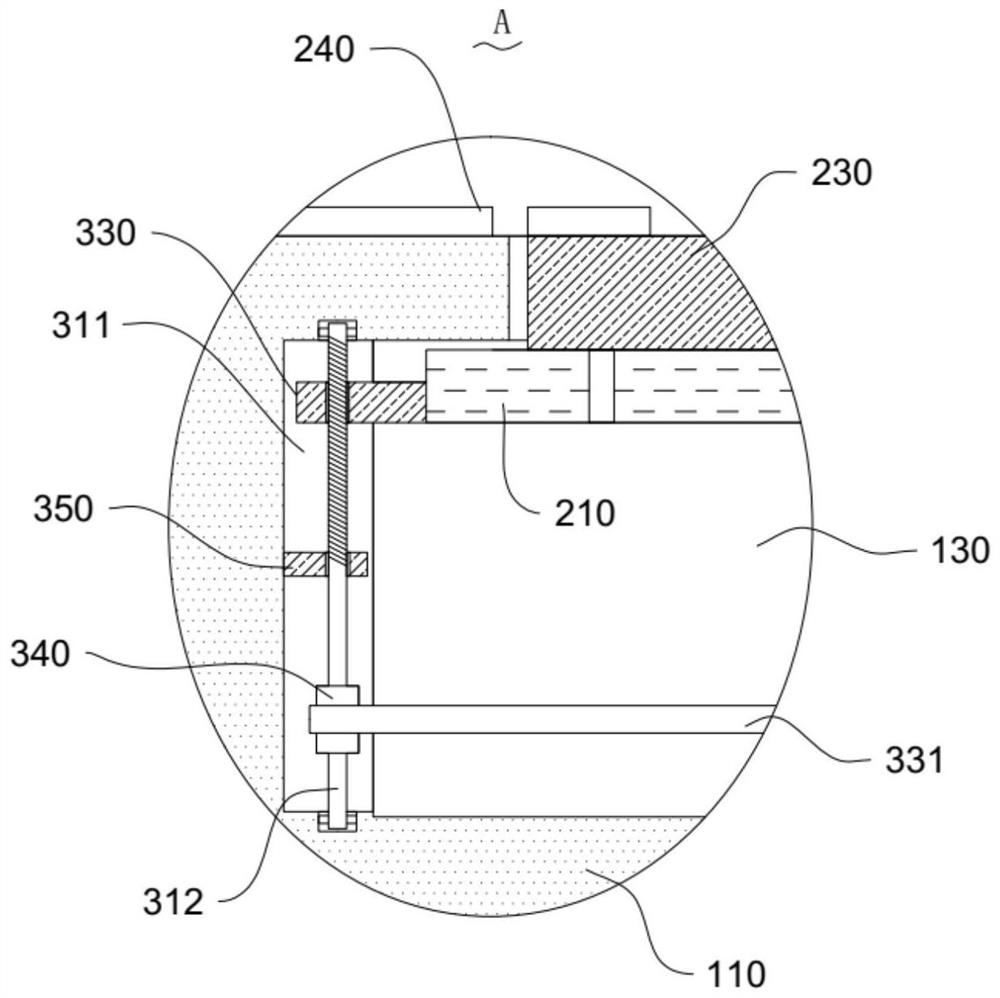
[0027] The mounting assembly 200 includes a mounting plate 210, an operation plate 230 and a cover plate 240, wherein, the mounting plate 210, the mounting plate 210 is slidingly connected with the inner wall of the cavity 130, and the mounting plate 210 is located in the cavity 130 Inside; the installation hole 220, the installation hole 220 is opened on the top inner wall of the cavity 130; the operation panel 230, the operation panel 230 is located in the installation hole 220, and the top of the operation panel 230 extends to Above the installation hole 220; a cover pl...

Embodiment 2

[0033] Based on the distribution automation terminal device provided in the first embodiment of the present application, the second embodiment of the present application proposes another distribution automation terminal device. The second embodiment is only a preferred mode of the first embodiment, and the implementation of the second embodiment will not affect the independent implementation of the first embodiment.

[0034] The second embodiment of the present invention will be further described below in conjunction with the drawings and implementation methods.

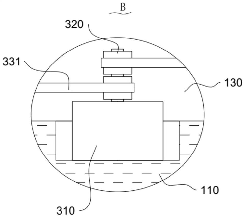
[0035] refer to Figure 4-Figure 6 The power distribution automation terminal equipment also includes two second grooves 351 on the side where the two lifting plates 330 are close to each other, and third grooves 352 are formed on both sides of the mounting plate 210, the The first wedge-shaped block 351a is slidably installed in the third groove 352, and the sides of the two wedge-shaped blocks that are far away fr...


PUM


Abstract

The invention provides power distribution automation terminal equipment. The power distribution automation terminal equipment comprises a terminal main body; a display screen which is fixedly mounted at the top of the terminal main body; a cavity which is formed in the terminal main body; a mounting plate which is in sliding connection with the inner wall of the cavity, wherein the mounting plate is located in the cavity; a mounting hole which is formed in the inner wall of the top of the cavity; an operation plate which is located in the mounting hole, and the top of the operation plate extends to the position above the mounting hole; a cover plate which is arranged at the top of the terminal main body in a sliding manner, wherein the cover plate is matched with the mounting hole; and a lifting mechanism which is mounted in the terminal main body. The power distribution automation terminal equipment provided by the invention has the advantages that the use is convenient, the operation is simple, the operation panel can be stored and protected, and the operation panel can be prevented from being accidentally touched.

Description

technical field [0001] The invention relates to the technical field of power distribution, in particular to a power distribution automation terminal device. Background technique [0002] Distribution Automation (DA) is a comprehensive information management system integrating computer technology, data transmission, control technology, modern equipment and management. Reduce operating costs and reduce the labor intensity of operators. In industrially developed countries, distribution system automation has received extensive attention. The distribution system automation in the United States, Japan, Germany, France and other countries has formed a set of substation automation, feeder segment switch measurement and control, capacitor bank adjustment control, user A distribution network management system (DMS) that integrates load control and remote meter reading systems. [0003] Most of the existing power distribution braking terminal equipment is a console, which is composed...

Claims


Application Information

Patent Timeline
IPC IPC(8): H02B15/00
CPCH02B15/00
Inventor 包义钊李瑶徐润关晨晨林小竺代启璨卢颖任庭昊毛杰覃禹铭
Owner GUIZHOU POWER GRID CO LTD
Why Eureka
Try Eureka