Display device, terminal device, display panel, and display device driving method

a technology of display device and terminal device, which is applied in the direction of instruments, computing, electric digital data processing, etc., can solve the problems of block-like unevenness, and display quality degradation, so as to suppress the deterioration of display image quality and high image quality

Active Publication Date: 2009-04-16
NEC LCD TECH CORP
View PDF14 Cites 45 Cited by
  • Summary
  • Abstract
  • Description
  • Claims
  • Application Information

AI Technical Summary

Benefits of technology

[0012]The present invention has been designed in view of such issues. An exemplary object of the present invention is to provide a display device which can achieve high image quality by suppressing deterioration of the display image quality which is generated when the division driving method is employed for a plural-viewpoint display device to which an image separating optical element such as a lenticular lens or a parallax barrier is provided, and to provide a terminal device, a display panel preferably used for such devices, as well as to a driving method of the display device.

Problems solved by technology

However, there has been found that block division causes deterioration in the display quality of the display device with the above-described block division driving method.
In this deterioration of the picture quality, luminance differences are generated between edges of the blocks and other parts in particular even when same video information is written thereto, which generates block-like unevenness.
As described, the driving method which supplies the video signals in a time-division manner generates deterioration in the display image quality caused due to the division.

Method used


Image

  • Display device, terminal device, display panel,  and display device driving method
  • Display device, terminal device, display panel,  and display device driving method
  • Display device, terminal device, display panel,  and display device driving method

Examples


Embodiment Construction

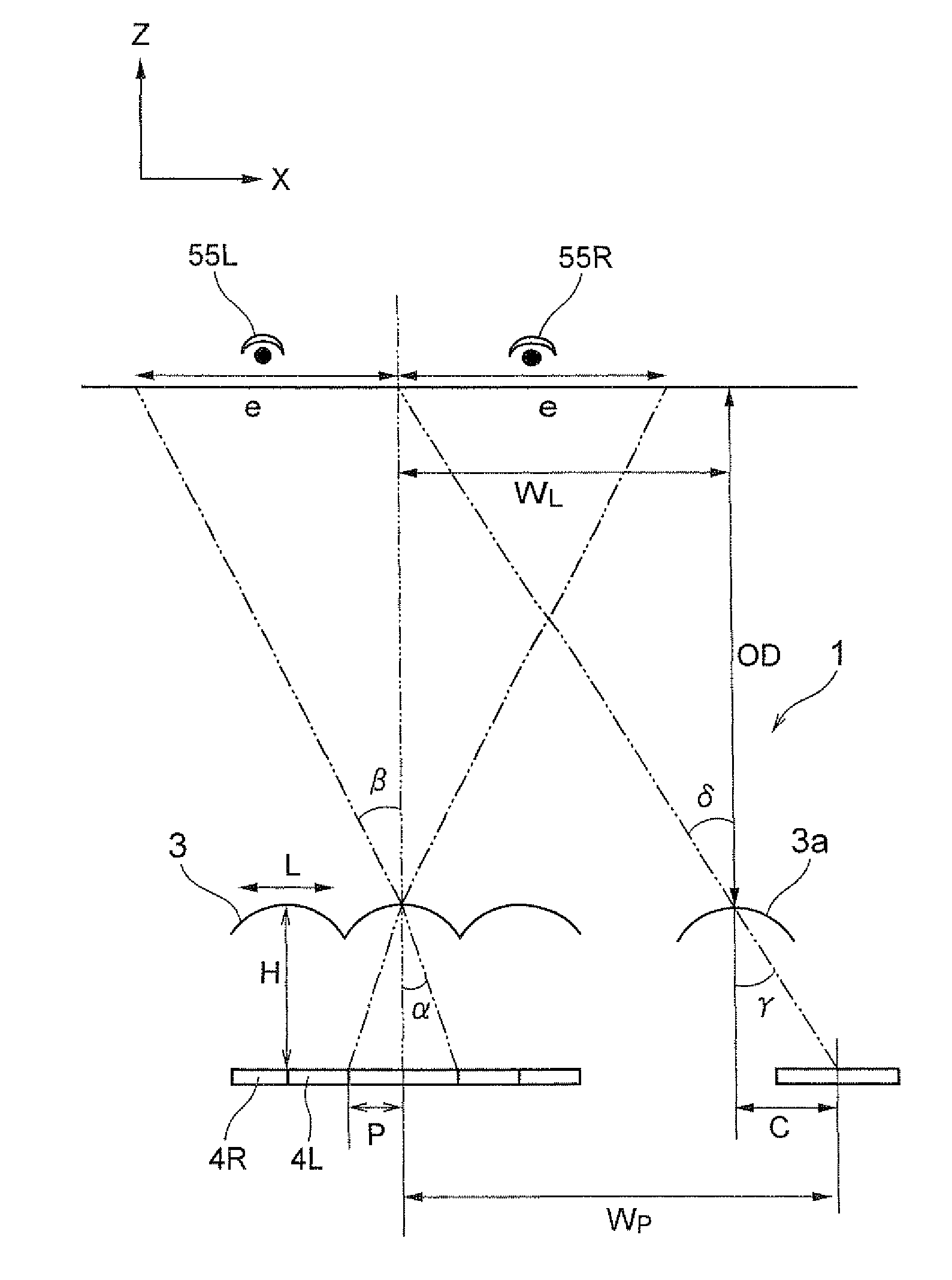
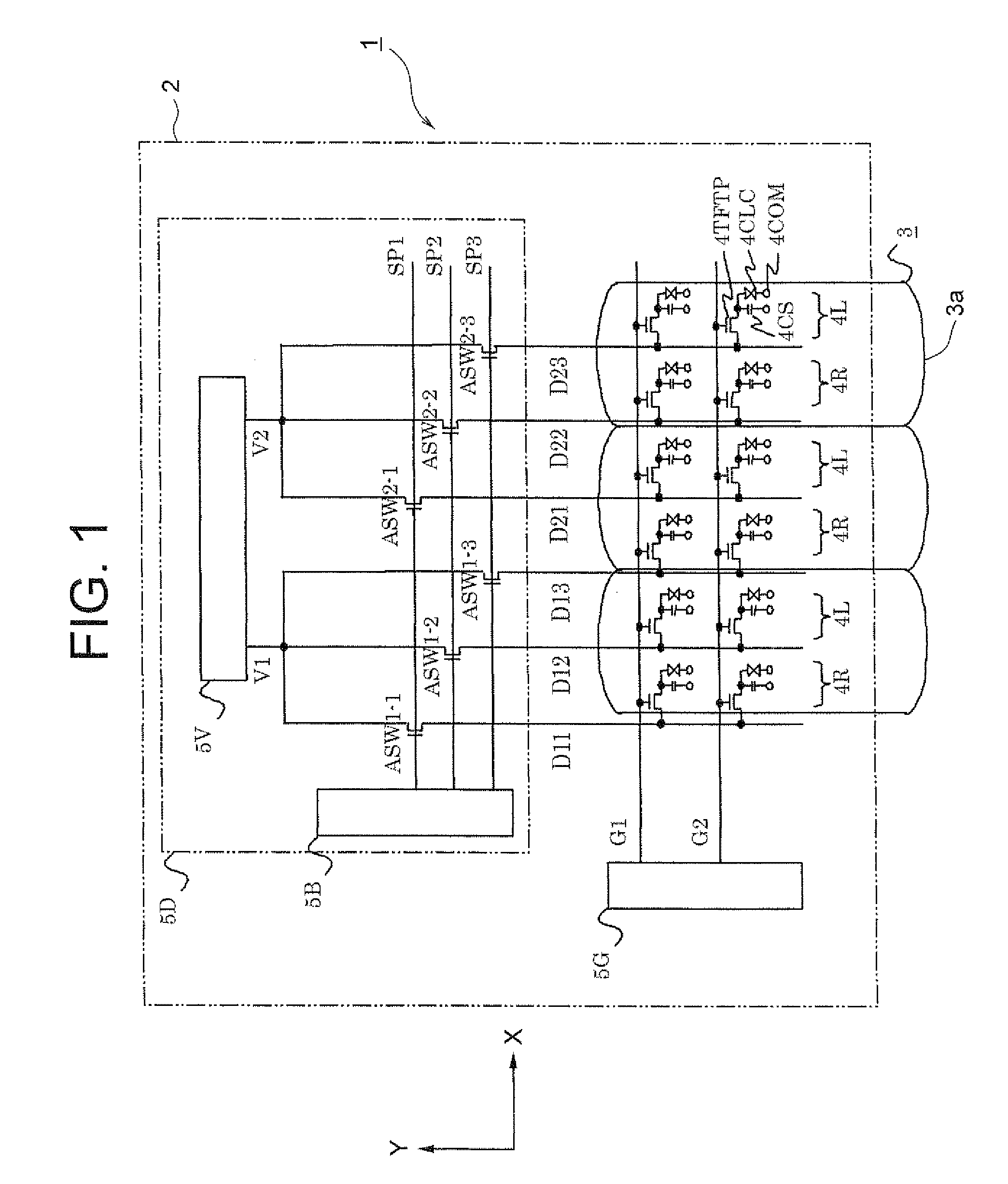
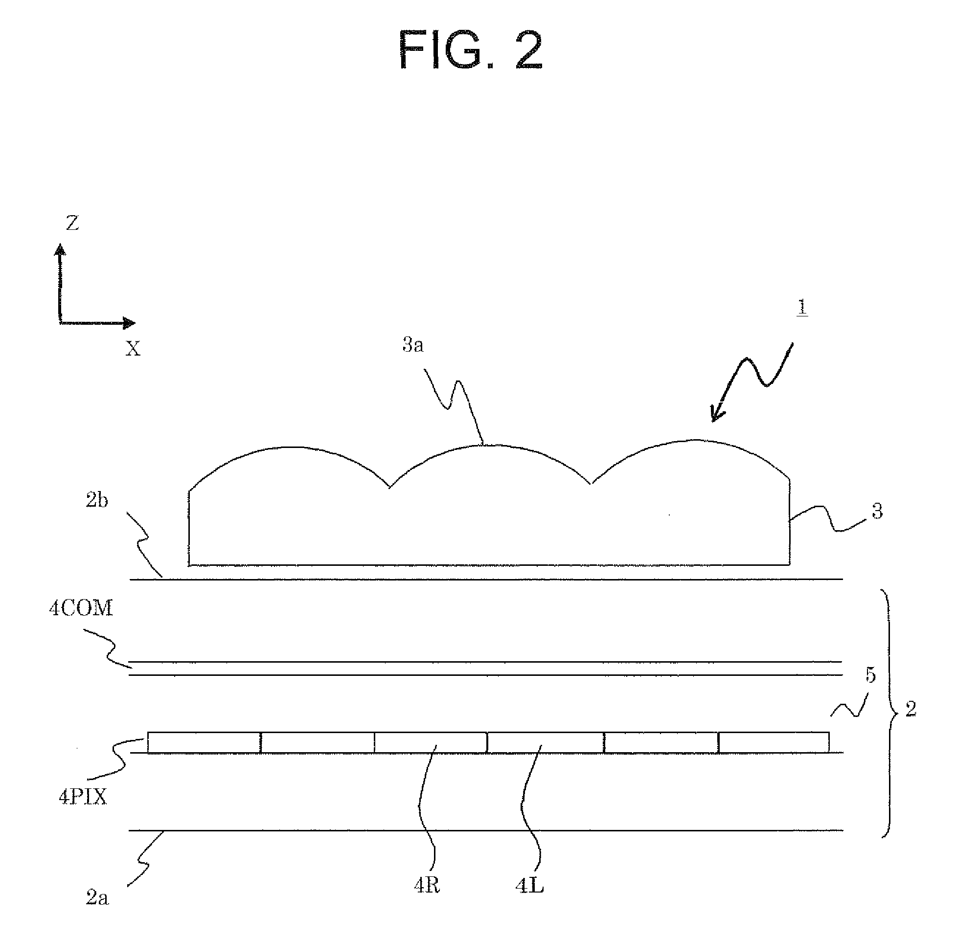
[0058]Hereinafter, a display device, its driving method, a terminal device, and a display panel according to exemplary embodiments of the invention will be described in a concrete manner by referring to the accompanying drawings. First, the display device, its driving method, the terminal device, and the display panel according to a first exemplary embodiment of the invention will be described. FIG. 1 is a top plan view showing the display device according to the first exemplary embodiment of the invention, which, in particular, shows a relation between electrical circuit blocks and a lenticular lens as an image separating device. FIG. 2 is a sectional view showing the display device according to this exemplary embodiment. FIG. 3 is a top plan view showing pixels of the display device according to this exemplary embodiment, and FIG. 4 is a perspective view showing a terminal device according to this exemplary embodiment.

[0059]The present invention can be characterized as follows. Th...


PUM


Abstract

To provide a plural-viewpoint display device having an image separating optical element such as a lenticular lens or a parallax barrier, which is capable of achieving a high image quality by suppressing deterioration in the display image quality caused when a block division driving method is employed, and to provide a terminal device, a display panel, and a driving method thereof, which can be preferably used for those devices. A pixel group configured with pixels for displaying a right-eye image includes a pixel connected to a data line phase-deployed in the first phase of a block division driving method, and a pixel connected to a data line phase-deployed in the third phase, and a pixel connected to a data line phase-deployed in the second phase. In this manner, it is designed to have no deviation in the phase deployment orders in the pixel groups for each viewpoint.

Description

CROSS-REFERENCE TO RELATED APPLICATIONS[0001]This application is based upon and claims the benefit of priority from Japanese patent application No. 2007-268422, filed on Oct. 15, 2007, and Japanese patent application No. 2008-234095, filed on Sep. 12, 2008, the disclosure of which is incorporated herein in its entirety by reference.BACKGROUND OF THE INVENTION[0002]1. Field of the Invention[0003]The present invention relates to a display device, a terminal device, a display panel, and a display device driving method, which are capable of displaying images to each of a plurality of viewpoints. More specifically, the present invention relates to a display device, a terminal device, a display panel, and a display device driving method, which are capable of suppressing deterioration in the image quality caused when writing video signal on a single row of pixels in a time division manner.[0004]2. Description of the Related Art[0005]Owing to the recent technical developments, display panel...

Claims


Application Information

Patent Timeline
Patent Type & Authority Applications(United States)
IPC IPC(8): G09G5/36G06F3/038G02B30/28G02B30/30
CPCG02B27/2214G09G3/003G09G3/3648G09G3/3611G09G2310/0297G09G2320/0233H04N13/0404G09G2300/0426H04N13/305H04N13/31H04N13/351H04N13/315H04N13/398G02B30/28G02B30/30G09G3/3688G09G2320/04G09G2320/028G02B30/27H04N2213/001
Inventor UEHARA, SHINICHISATOU, TETSHUSHI
Owner NEC LCD TECH CORP
Why Eureka
Try Eureka