
Polarized phase microscopy

a phase microscopy and polarized technology, applied in the field of phase microscopy imaging systems, can solve the problems of phase rings, difficult correction of optical effects through mathematical techniques such as digital deconvolution, and insufficient visualization with white light in many instances

Inactive Publication Date: 2009-04-16
APPLIED PRECISION INC
View PDF4 Cites 3 Cited by
  • Summary
  • Abstract
  • Description
  • Claims
  • Application Information

AI Technical Summary

Benefits of technology

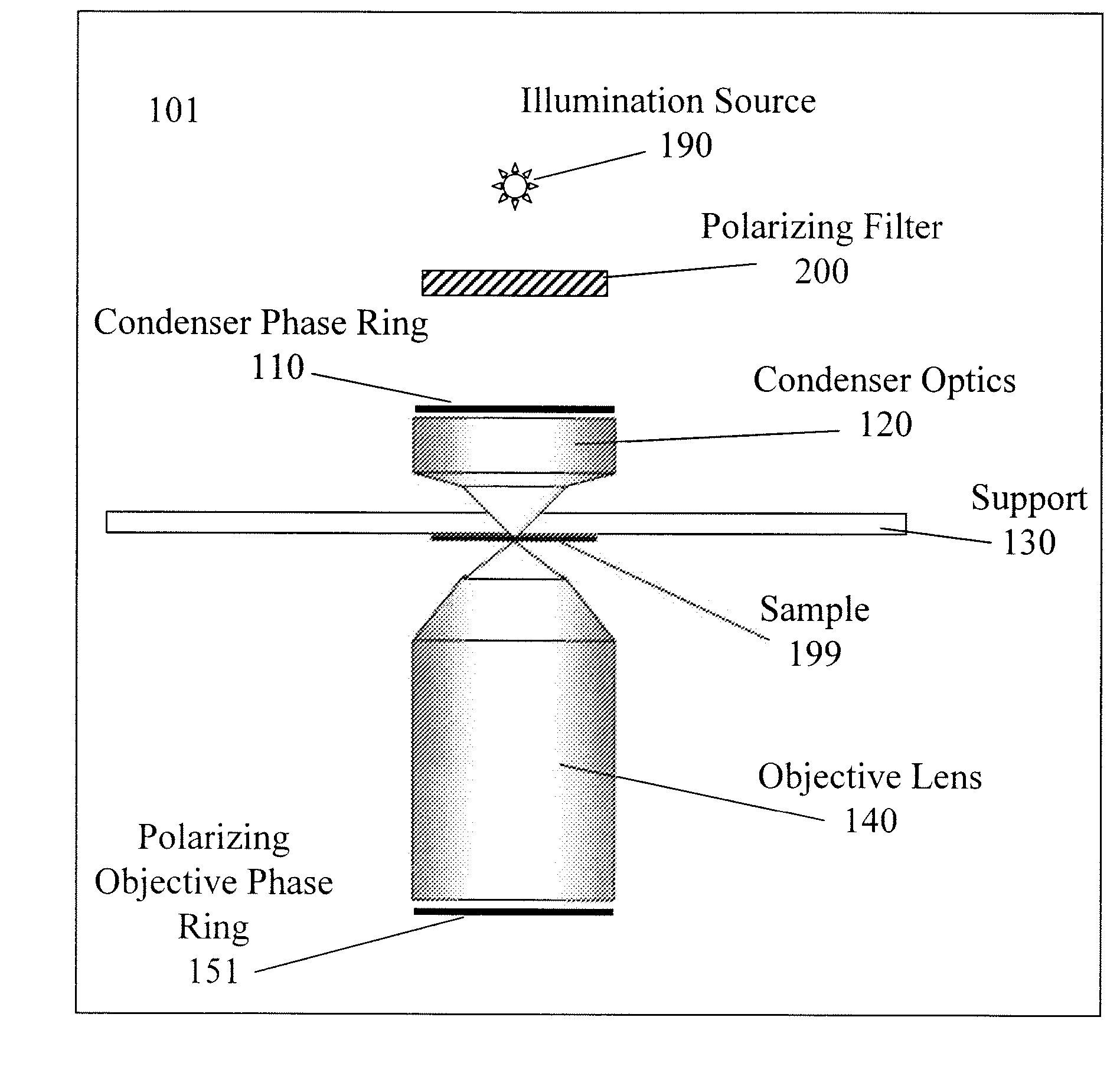
"The present invention relates to a system and method for generating phase contrast microscopy images with minimal interference to other microscopy modalities, such as fluorescence microscopy. The system includes a polarizing objective phase ring that controls the attenuation of light in a specific plane, allowing for selective control of interference with the intensity and optical quality of other microscopy modalities. The method involves providing illumination with a source, selectively plane-polarizing the illumination incident on the condenser lens, and selectively plane-polarizing emission light incident on the polarizing objective phase ring. The technical effect of this invention is the ability to generate high-quality phase microscopy images without compromising the intensity and optical quality of other microscopy modalities."

Problems solved by technology

The cells themselves are most often devoid of inherent absorptions of light, so visualization with white light is not sufficient in many instances.
Recent studies have demonstrated, however, that DIC microscopy introduces spatial artifacts into fluorescence microscopy systems by altering the Point Spread Function (PSF) of the optical train.
This artifact is particularly disadvantageous because it is an asymmetrical blurring of the PSF, rendering correction of the optical effect through mathematical techniques such as digital deconvolution very difficult.
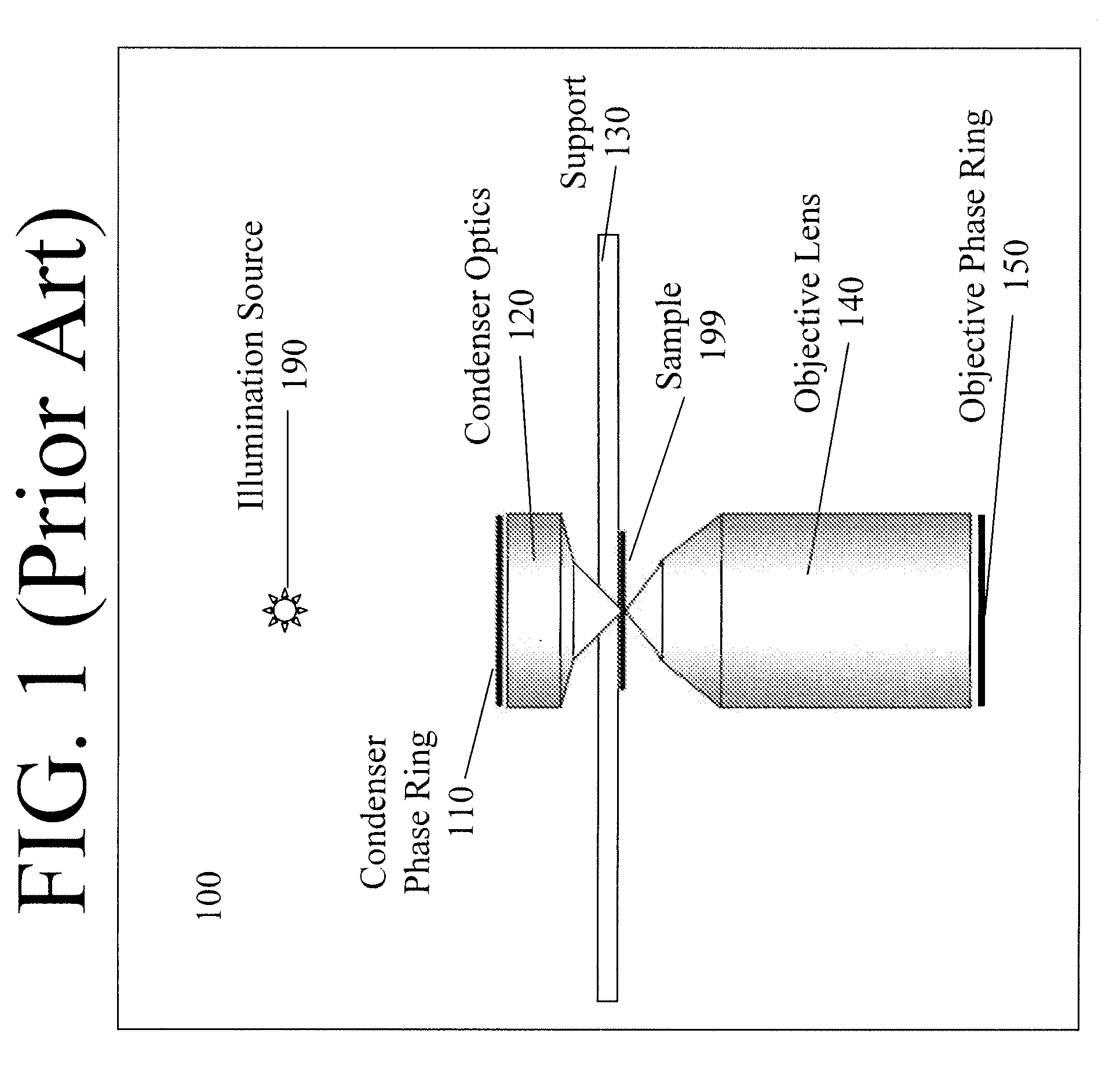
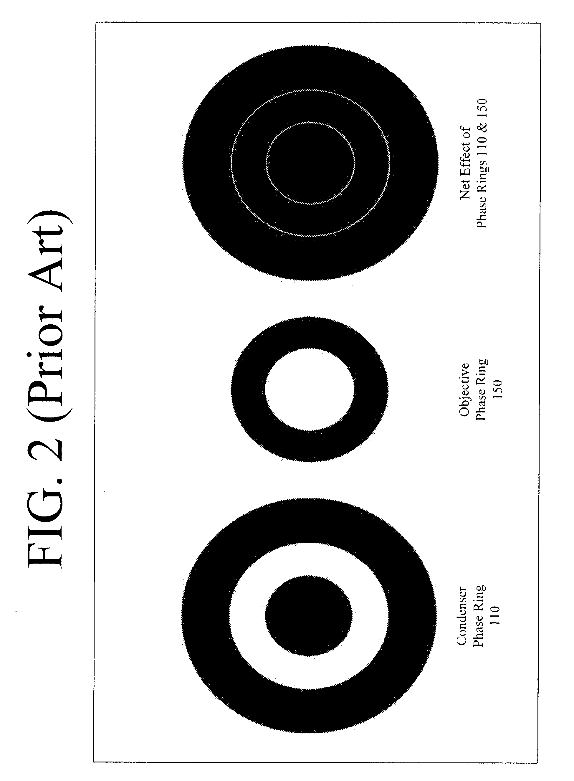
The introduction of phase rings, however, also interferes with the total intensity of the light collected by the microscope because some of the light that would normally pass through the objective lens is attenuated by one or more of the rings.
Consequently, phase microscopy is most often not utilized with fluorescence microscopy applications.
Conventional technology is deficient at least to the extent that the best contrast generating method for use in conjunction with fluorescence microscopy applications tends to distort the very fluorescence whose localization is under investigation.

Method used


Image

  • Polarized phase microscopy
  • Polarized phase microscopy
  • Polarized phase microscopy

Examples


Embodiment Construction

[0012]Aspects of the present invention relate to generating and acquiring phase contrast microscope images while minimizing interference with the intensity and optical quality of other microscopy modalities, and without requiring the removal of any optical components. As set forth in more detail below, instead of using an entirely opaque annulus, or phase ring, in the back focal plane of the objective lens, a polarizing annulus, or polarizing phase ring, may be used. In accordance with the structural arrangements set forth herein, attenuated light may be selectively controlled, i.e. transparency may be selectively provided to emission light occurring in a predetermined plane. Accordingly, a polarizing objective phase ring effective for enabling phase microscopy may decrease interference with normal usage of the microscope for other applications such as, for example, fluorescence microscopy.

[0013]In accordance with one embodiment, for example, a method as disclosed herein may compris...


PUM


Abstract

A system and method of generating and acquiring phase contrast microscope images while minimizing interference with the intensity and optical quality of other microscopy modalities employing polarization and attenuation strategies for phase microscopy applications. A plane polarizing objective phase ring may be used in conjunction with a phase microscopy apparatus. Attenuated light may be controlled such that transparency may be selectively provided with respect to light in a predetermined plane. Illumination outside of the predetermined plane may be selected for phase microscopy applications. Accordingly, a polarizing objective phase ring effective for enabling polarized phase microscopy may reduce interfere with normal usage of the microscope for other applications such as, for example, fluorescence microscopy.

Description

CROSS REFERENCE TO RELATED APPLICATIONS[0001]The present application is a continuation application of U.S. patent application Ser. No. 11 / 552,953, filed Oct. 26, 2006, which claims benefit from the priority of U.S. Provisional Patent Application No. 60 / 730,482, filed Oct. 25, 2005, entitled “Polarized Phase Microscopy,” which application is incorporated herein by reference and for all purposes. The present application is related to U.S. nonprovisional application Ser. No. 10 / 742,507, filed Dec. 19, 2003 and now abandoned, which applications are incorporated herein by reference and for all purposes.FIELD OF THE INVENTION[0002]Aspects of the present invention relate generally to phase microscopy imaging systems, and more particularly to a system and method employing polarized illumination and attenuation strategies for phase microscopy applications.DESCRIPTION OF THE RELATED ART[0003]When performing fluorescence microscopy on living cells, tissues, and organisms, it is often desirable...

Claims


Application Information

Patent Timeline
Patent Type & Authority Applications(United States)
IPC IPC(8): G02B21/06
CPCG02B21/0092G02B27/52G02B21/16G02B21/14
Inventor GOODWIN, PAUL C.
Owner APPLIED PRECISION INC
Learn More