High Flow Therapy Artificial Airway Interfaces and Related Methods

a technology of artificial airway and high flow, applied in the field of respiratory medicine, can solve the problems of high and possibly dangerous pressure formation, affecting the patient's breathing, and affecting the patient's breathing, and achieve the effect of increasing the upper airway pressur

Active Publication Date: 2009-04-23
RESMED LTD
View PDF23 Cites 127 Cited by
  • Summary
  • Abstract
  • Description
  • Claims
  • Application Information

AI Technical Summary

Benefits of technology

[0010]Embodiments of the present invention address deficiencies of the art in respect to patient interfaces and provide a novel and non-obvious device, system and method for providing patient interfaces for use with a non-sealing respiratory gas delivery system. In an embodiment of the invention, a nasal cannula including a nasal cannula interface body and a flange configured to partially impede the egress of respiratory gasses and to increase upper airway pressure delivered to a user of the nasal cannula is provided. In another aspect of the embodiment, the flange has a shape selected from the group consisting of a slotted, vented or slitted design and configured to partially impede the egress of respiratory gasses, is provided.

Problems solved by technology

Since HFT is traditionally flow based (the flow rate is set), a seal could cause development of high and possibly dangerous pressures to form.
Moreover, a seal may prevent proper exhalation.
The airway pressures of patients are rarely, measured or regulated during HFT due to the lack of a conveniently available device or system for clinicians to use.
As such, mouth breathing is a further limitation to creating upper airway pressures which may be desirable for use in therapy.
Nasal insufflation may have low efficacy in patients with nasal congestion or poorly defined nasal passages.

Method used


Image

  • High Flow Therapy Artificial Airway Interfaces and Related Methods
  • High Flow Therapy Artificial Airway Interfaces and Related Methods
  • High Flow Therapy Artificial Airway Interfaces and Related Methods

Examples


Embodiment Construction

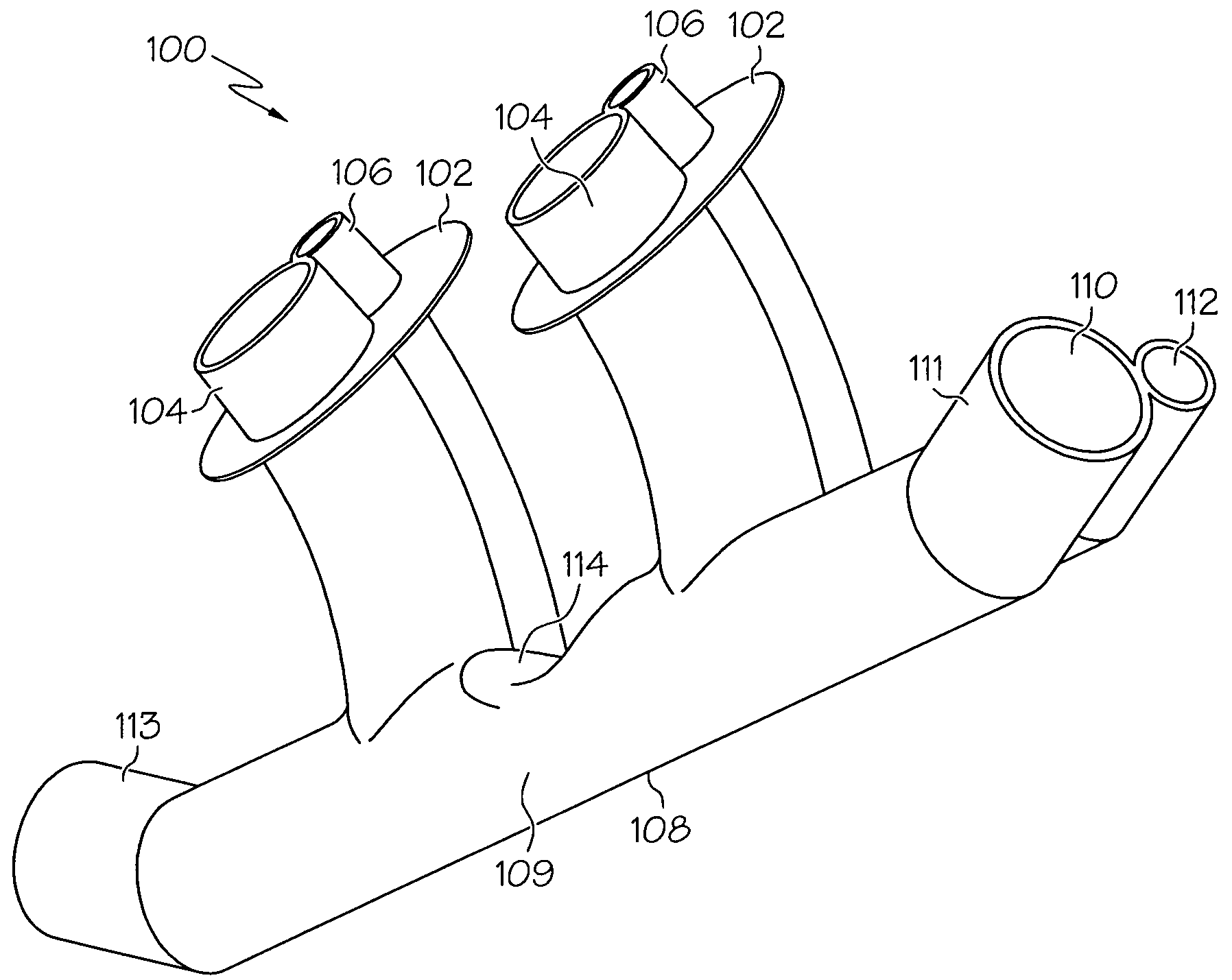
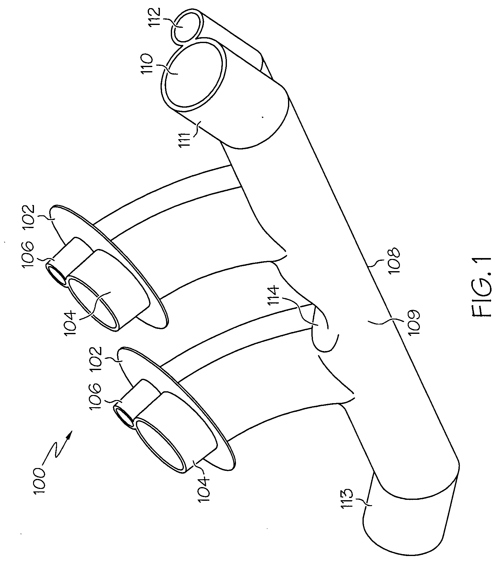
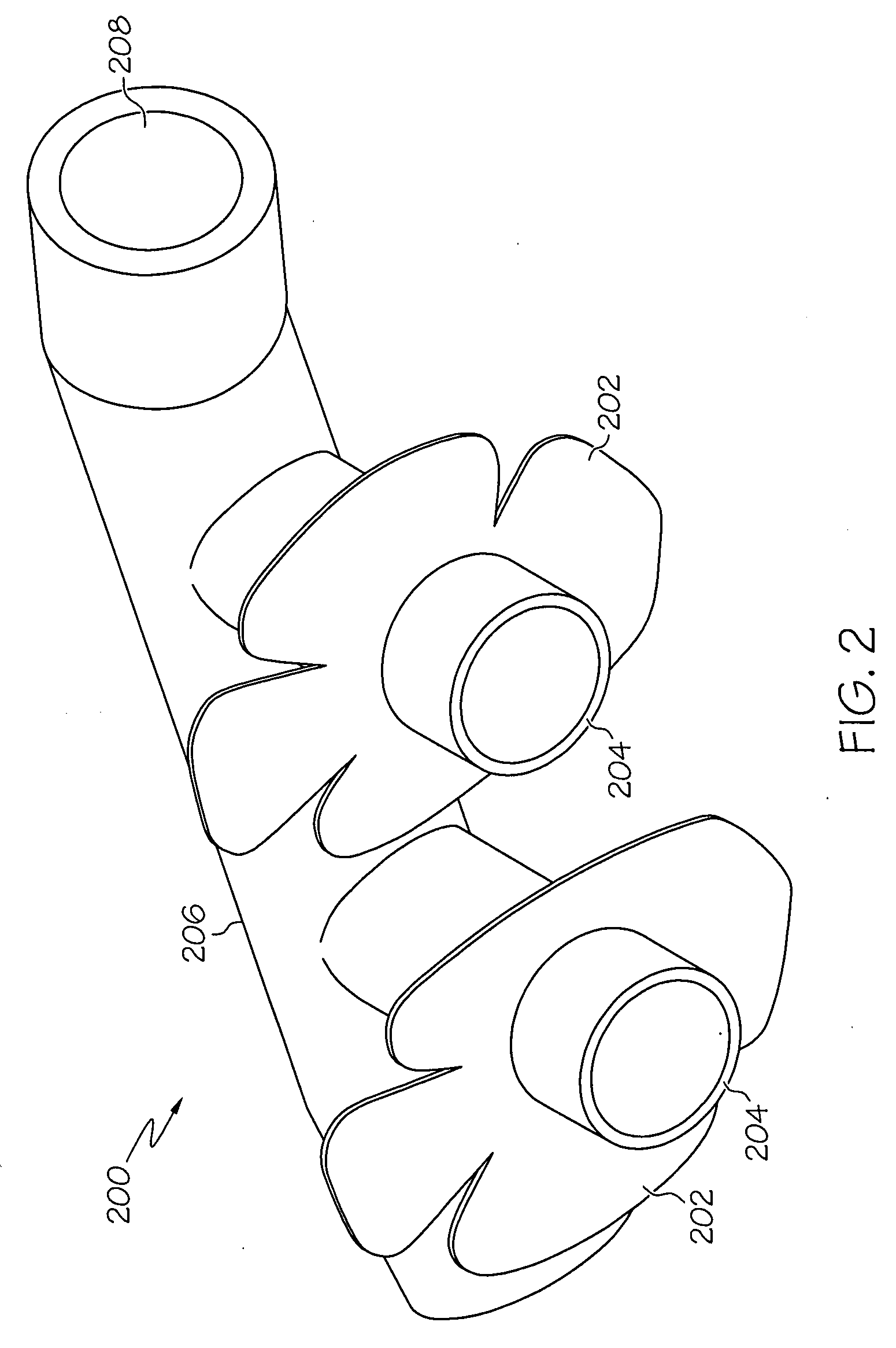
[0029]The present disclosure relates to a design of nasal cannula with features to enhance airway pressures without creating a seal around the cannula in the nares. The design also takes into consideration the need for safety and thereby avoids creation of a seal around the cannula inside the nares.

[0030]Certain configurations utilize a dual lumen approach where one lumen is for the gas flow and the other lumen is used to measure airway pressures. The capability to monitor airway pressures includes the desire to have greater control over airway pressures, and the ability to increase them.

[0031]In an embodiment of the invention, a nasal cannula including a nasal cannula interface body and a flange configured to partially impede the egress of respiratory gasses and to increase upper airway pressure delivered to a user of the nasal cannula is provided. In another aspect of the embodiment, the flange has a shape selected from the group consisting of a slotted, vented or slitted design a...


PUM


Abstract

Embodiments of the present invention provide a device, system and method for providing high flow therapy interfaces for use in the treatment of respiratory conditions and in assisted respirations. In an embodiment of the invention, a nasal cannula for delivery of respiratory gases can include at least one nasal insert and at least one flange coupled to the at least one nasal insert where the at least one flange is configured to partially impede the egress of respiratory gasses delivered to an upper airway of a patient is provided. In another embodiment, a flange has a shape selected from the group consisting of a slotted, vented or slitted design and configured to partially impede the egress of respiratory gasses. In yet another embodiment, an oral interface for delivery of high flow therapy to the upper airway of a patient can include a gas diffuser that includes a terminus housing having a plurality of holes to allow the delivery of respiratory gases. In yet another embodiment, a high flow therapy interface includes at least one nasal cannula and at least one oral interface in fluid communication with the at least one nasal cannula, the oral interface can include at least one port for delivery of respiratory gases to the mouth of a patient.

Description

CROSS-REFERENCE TO RELATED APPLICATIONS[0001]This application claims the benefit of U.S. Provisional Patent Application Ser. No. 61 / 009,702, filed on Dec. 31, 2007, and U.S. Patent Application Ser. No. 11 / 999,675, filed Dec. 6, 2007, which is a continuation-in-part of U.S. patent application Ser. No. 11 / 638,981, filed on Dec. 14, 2006, which is a continuation-in-part application of U.S. patent application Ser. No. 11 / 520,490, filed on Sep. 12, 2006, which claims the benefit of U.S. Provisional Patent Application Ser. No. 60 / 716,776, filed Sep. 12, 2005, U.S. Provisional Patent Application Ser. No. 60 / 750,063, filed on Dec. 14, 2005; U.S. Provisional Patent Application Ser. No. 60 / 792,711, filed on Apr. 18, 2006; and U.S. Provisional Patent Application Ser. No. 60 / 852,851, filed on Oct. 18, 2006, the entirety of all of which are incorporated by reference herein.BACKGROUND[0002]1. Statement of the Technical Field[0003]The present disclosure relates generally to respiratory interfaces,...

Claims


Application Information

Patent Timeline
Patent Type & Authority Applications(United States)
IPC IPC(8): A61M16/00
CPCA61M16/0666A61M16/1075A61M16/12A61M16/16A61M2016/0024A61M2016/0027A61M16/125A61M2202/0208A61M2210/0618A61M2210/0625A61M16/0057A61M16/0493A61M16/0677A61M2016/1025A61M16/0858A61M16/0003A61M16/0605A61M16/0096A61M16/0875A61M2016/0661A61M2205/3331
Inventor LANDIS, ROBERT M.LEWIS, CHARLES A.
Owner RESMED LTD
Why Eureka
Try Eureka