Activating a Well System Tool

a technology of well system and tool, which is applied in the field of activating a well system tool, can solve the problems of increasing the probability of being able to shut down the well, the personnel may need to quickly abandon the well, etc., and achieve the effect of facilitating the monitoring of an actuated safety devi

Active Publication Date: 2016-09-15
SAUDI ARABIAN OIL CO
View PDF6 Cites 11 Cited by
  • Summary
  • Abstract
  • Description
  • Claims
  • Application Information

AI Technical Summary

Benefits of technology

[0027]Various implementations of a remotely-activated well shut-in system may include one, some, or all of the following features. For example, a remotely-activated well shut-in system may provide additional operational safety through the ability to function part of a well safety device (for example, a preventer) at a safe distance (for example, yards to miles) from a drilling rig. As another example, the remotely-activated well shut-in system may allow for a rig crew to evacuate a drill site location, while also providing an ability to monitor or monitor and function a safety device to shut-in and isolate the well until such time that emergency crews or suitably trained third party personnel may enter the proximity of the rig-site. As a further example, the remotely-activated well shut-in system may allow remote shut-in for a terranean surface based well during a time period (minutes, hours, days) when the well is considered out of control. As an even further example, the remotely-activated well shut-in system may facilitate monitoring of an actuated safety device (for example, preventer or other safety device) from a safe distance from an out of control well. The remotely-activated well shut-in system may also increase a probability of being able to shut-in the well during a well control incident. As yet another example, the remotely-activated well shut-in system may be used with a “dry tree” (for example, land-based or shallow water surface deployed) BOP system. Further, the remotely-activated well shut-in system may be an independent system that can be used to remotely-activate a safety device in either a new integrated BOP control system construction (for example, new BOP stack) or retrofit well construction (for example, retrofit BOP stack and HPU / Controls).

Problems solved by technology

In some situations, however, well personnel may need to quickly abandon a rig prior to implementation and confirmation of such shut-in operations.
The remotely-activated well shut-in system may also increase a probability of being able to shut-in the well during a well control incident.

Method used


Image

  • Activating a Well System Tool
  • Activating a Well System Tool
  • Activating a Well System Tool

Examples


Embodiment Construction

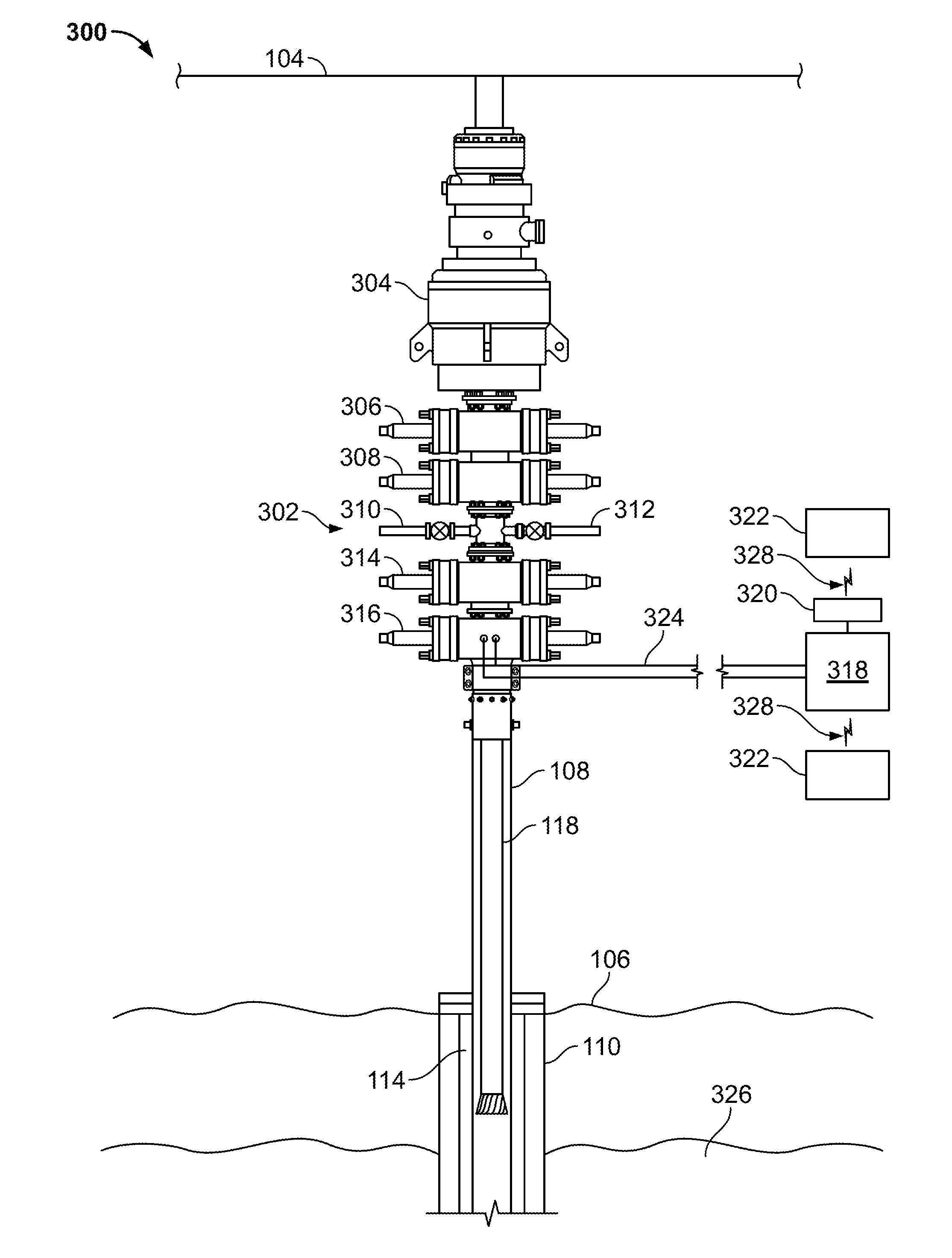
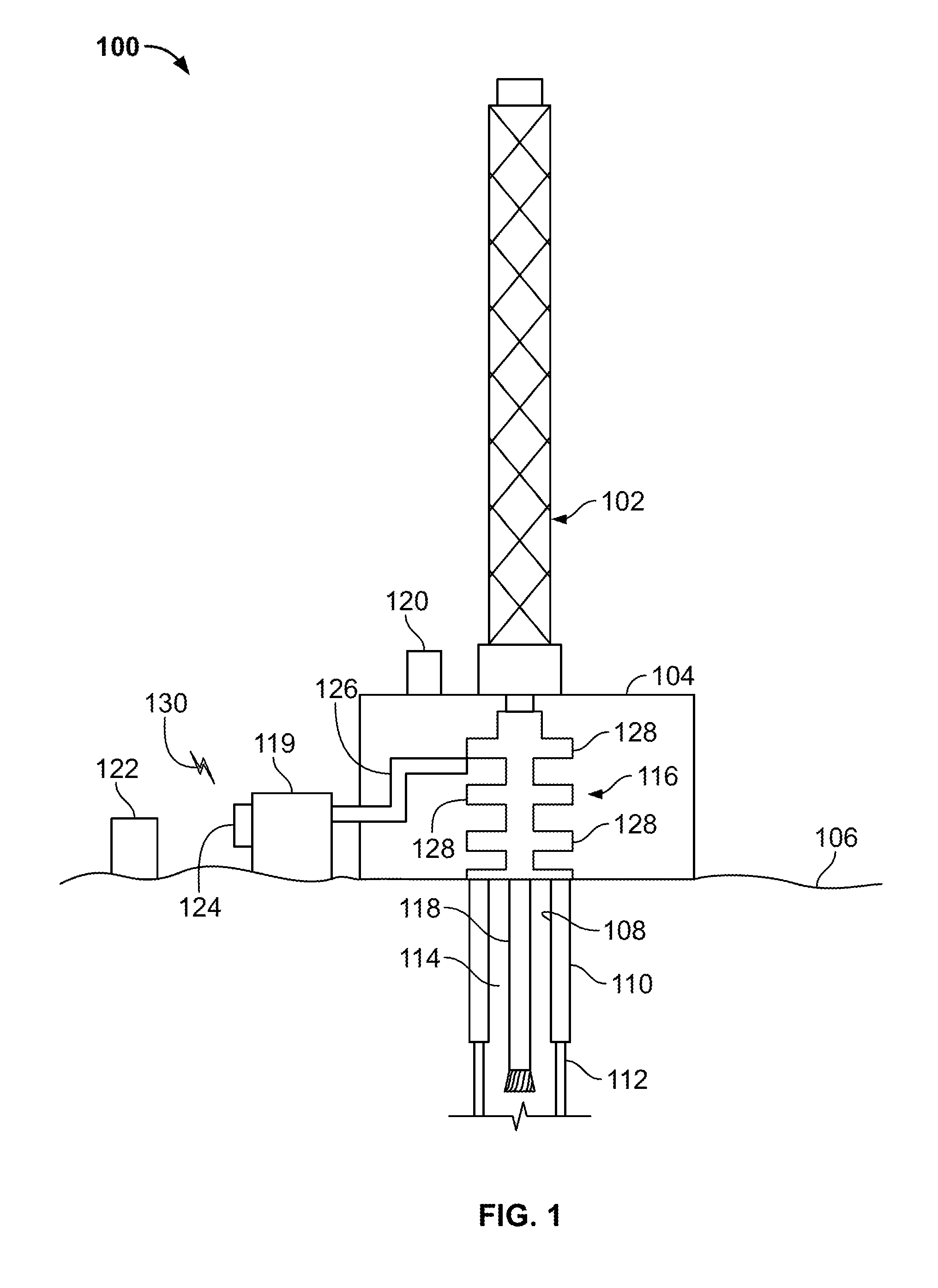
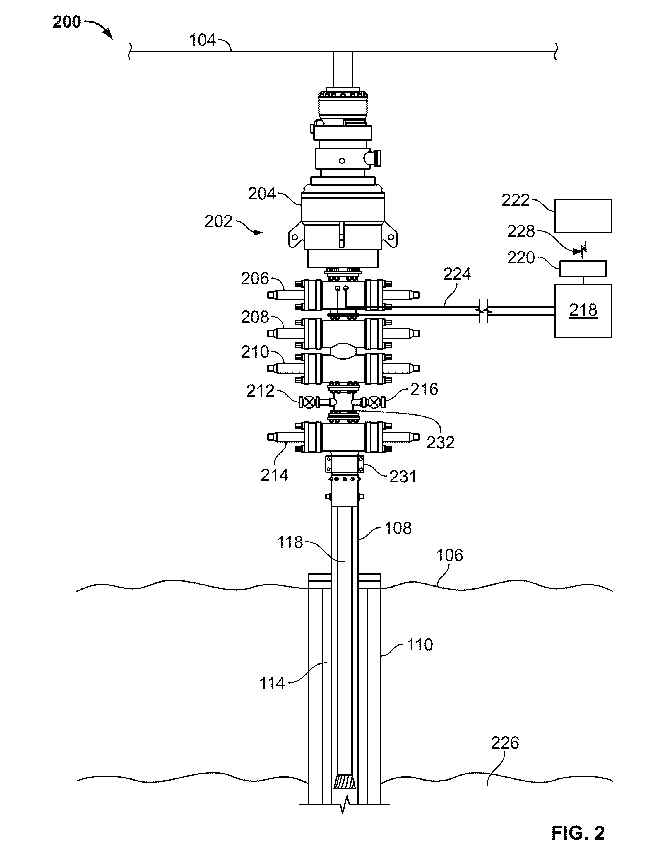
[0035]The present disclosure relates to a remotely-activated well shut-in system that is operable to remotely activate a well shut-in from a location remote from a rig when rig evacuation is occurring or has occurred. In some aspects, the remotely-activated well shut-in system includes a local control unit operable to activate a BOP power unit (for example, a hydraulic power unit or electrical power unit) in order to actuate a preventer to shut-in the well. In some aspects, the remotely-activated well shut-in system includes a remote control unit operable to transmit a signal to the local control unit to initiate the shut-in procedure. In some cases, the remote control unit initiates the shut-in procedure through a wireless communication remote from the rig by tens to hundreds of yards, a mile, or more than several miles, to ensure safety of the rig personnel. In some aspects, the remotely-activated well shut-in system may initiate the shut-in procedure of a land-based or shallow wa...


PUM


Abstract

A well system includes a local control unit configured to communicably couple to a well shut-in assembly at a well site, the well shut-in assembly operable to shut-in a wellbore based on a command from the local control unit; and a remote control unit configured to wirelessly communicate a line-of-sight airborne wireless signal, at a location remote from the local control unit and the well site, to initiate the command from the local control unit to the well shut-in assembly.

Description

CROSS-REFERENCE TO RELATED APPLICATION[0001]This application claims priority under 35 U.S.C. §119 to U.S. Provisional Patent Application Ser. No. 62 / 130,212, filed Mar. 9, 2015, and entitled “Activating a Well System Tool,” the entire contents of which are incorporated herein by reference.TECHNICAL BACKGROUND[0002]This disclosure relates to activating a well system tool and more particularly, to remotely activating a well system tool in an emergency condition.BACKGROUND[0003]In some well control incidents, such as those associated with well blow outs, fires, or otherwise, rig personnel have sufficient time to make the well secure by following predetermined operating procedures. Such operating procedures may involve shutting a well in, for example, preventing a hydrocarbon fluid from escaping the well bore or casing at a terranean surface. For example, a shut-in during a drilling operation may include stopping rotation of a drill string, raising or lowering the drill string with dril...

Claims


Application Information

Patent Timeline
Patent Type & Authority Applications(United States)
IPC IPC(8): E21B33/06E21B47/06
CPCE21B33/06E21B47/065E21B47/06E21B34/16E21B47/07
Inventor AFFLECK, MICHAEL
Owner SAUDI ARABIAN OIL CO
Why Eureka
Try Eureka