
Cover device for compact flourescent lamps

a technology for compact fluorescent lamps and covers, which is applied in the direction of lighting support devices, sustainable buildings, lighting and heating equipment, etc., can solve the problems of cfls still having cfl bulbs, cfls with an aesthetically pleasing look, and cfls are relatively expensive, so as to improve the appearance of compact fluorescent lamps, reduce costs, and change the optical

Inactive Publication Date: 2009-04-23
ADAPTIVE LIGHTING SOLUTIONS
View PDF35 Cites 5 Cited by
  • Summary
  • Abstract
  • Description
  • Claims
  • Application Information

AI Technical Summary

Benefits of technology

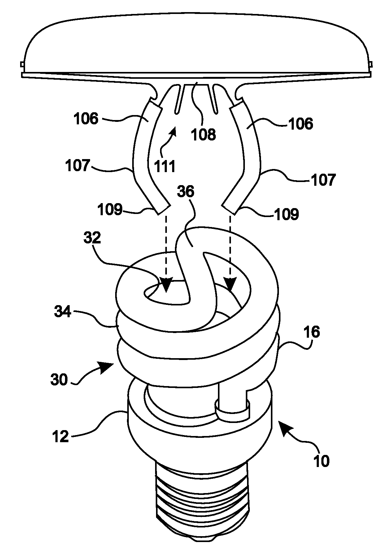
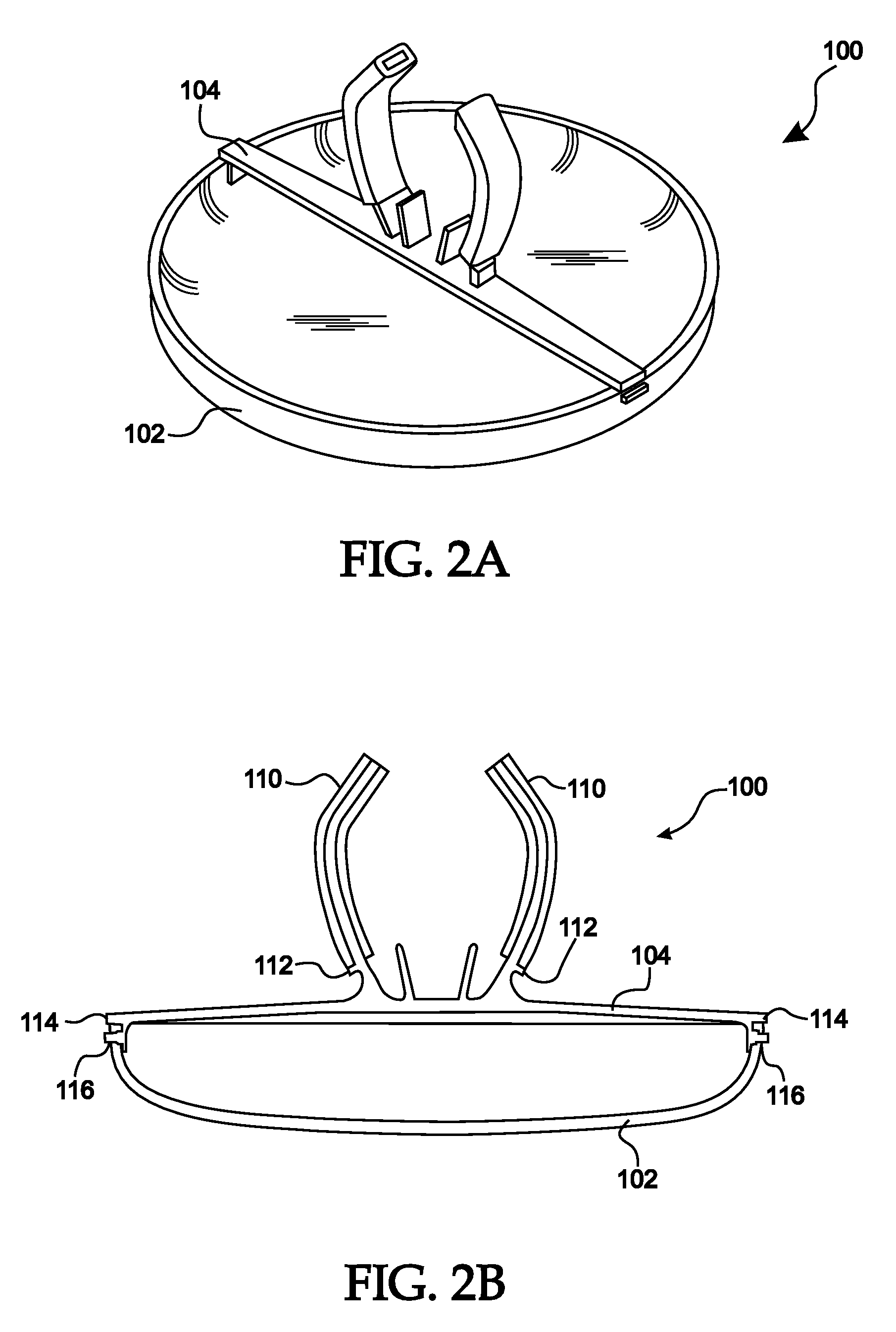
[0009]A device for enhancing the appearance of a compact fluorescent lamp (CFL) and changing the optical properties of light emitted by the CFL is provided. The cover device of the present disclosure is a lower cost, yet aesthetically acceptable recessed CFL lighting solution for residential and commercial applications. The cover device of the present disclosure provides a low cost attachable cover or lens accessory to a standard spiral or linear CFL bulb to permit it to be used in recessed and other lighting applications, while greatly improving its aesthetic appearance. The techniques of the present disclosure will offer more color / decorative properties and options than a typical CFL PAR type lamp.
[0013]In yet another aspect, each of the at least two fingers includes a material for increasing the friction between each of the at least two fingers and the inner surface of the compact fluorescent lamp.

Problems solved by technology

However, CFL bulbs still have three main drawbacks: 1) CFLs do not have an aesthetically pleasing look, 2) CFLs are relatively expensive, and 3) the least expensive CFL bulbs often have very high color temperatures (e.g., cooler, bluer) than conventional incandescent bulbs.
However, for recessed lighting applications the reflector type CFL's are quite expensive, typically in the $6 to $7 range.

Method used


Image

  • Cover device for compact flourescent lamps
  • Cover device for compact flourescent lamps
  • Cover device for compact flourescent lamps

Examples


Embodiment Construction

[0038]Preferred embodiments of the present disclosure will be described hereinbelow with reference to the accompanying drawings. In the following description, well-known functions or constructions are not described in detail to avoid obscuring the invention in unnecessary detail. Throughout the drawings, like reference numerals represent like elements.

[0039]A cover device for enhancing the appearance of a compact fluorescent lamp (CFL) and changing the optical properties of light emitted by the CFL is provided. The device of the present disclosure includes a family of parabolic, curved or flat lens covers that can be easily attached to a standard spiral or linear compact fluorescent light bulb. The cover of the device is configured to have a diameter matching standard PAR type incandescent lamps (e.g. R20, R30, PAR 38, R40, etc.) so that cover will fit into existing recessed lighting products made to accommodate these standard PAR or R bulb sizes. In use, a parabolic, curved or flat...


PUM


Abstract

A device for enhancing the appearance of a compact fluorescent lamp (CFL) and changing the optical properties of light emitted by the CFL is provided. The device for a compact fluorescent lamp (CFL) includes a cover configured for obscuring the compact fluorescent lamp; and an attachment mechanism configured for coupling the cover to the compact fluorescent lamp by engaging an inner surface of the compact fluorescent lamp. The attachment mechanism includes at least two resilient fingers for engaging at least two spaced apart inner surfaces of the compact fluorescent lamp.

Description

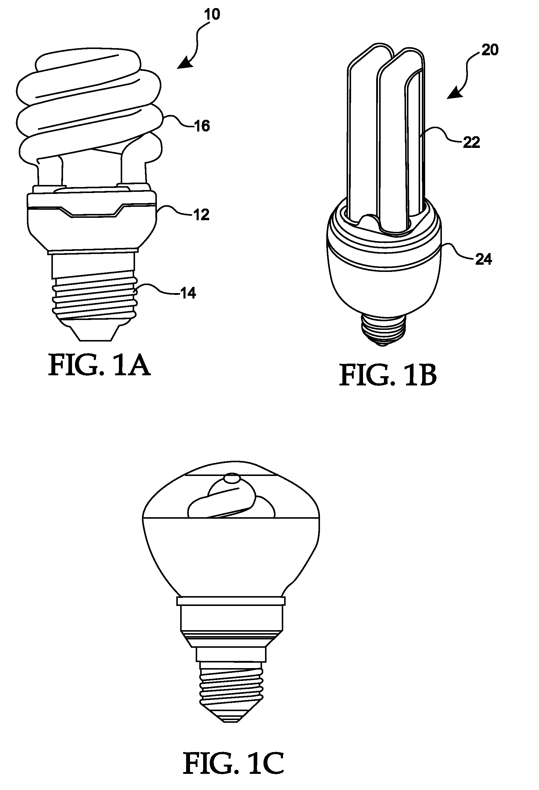
BACKGROUND[0001]1. Field[0002]The present disclosure relates generally to light bulbs and lamp assemblies, and more particularly, to a cover for a compact fluorescent lamp (CFL) which improves the aesthetic appearance of the compact fluorescent lamp while providing color and optical options not available in conventional compact fluorescent lamps.[0003]2. Description of the Related Art[0004]A compact fluorescent lamp (CFL), also known as a compact fluorescent light bulb, is a type of fluorescent lamp designed to replace an incandescent lamp. Many CFLs can fit in existing incandescent light fixtures. After 20 or more years of technology evolution, compact fluorescent lamps (CFLs) as shown in FIG. 1 are starting to be more widely used as replacements for incandescent bulbs due to their much greater energy efficiency.[0005]The most common form of CFL is the spiral type shown in FIG. 1A. The spiral CFL 10 includes a base 12 configured for retaining the electronics necessary for the bulb....

Claims


Application Information

Patent Timeline
Patent Type & Authority Applications(United States)
IPC IPC(8): F21V11/00
CPCF21V9/08F21V11/16Y02B20/19F21Y2103/02F21V17/04F21Y2103/30Y02B20/00
Inventor BERNHARDT, GARY COLINPAWELKO, WOJCIECHFUSCO, MICHAELSAVONA, MICHAEL A.HACKER, JONATHAN
Owner ADAPTIVE LIGHTING SOLUTIONS
Learn More