Method, apparatus and computer program for migrating records in a database from a source database schema to a target database schema
- Summary
- Abstract
- Description
- Claims
- Application Information
AI Technical Summary
Benefits of technology
Problems solved by technology
Method used
Image
Examples
example 1
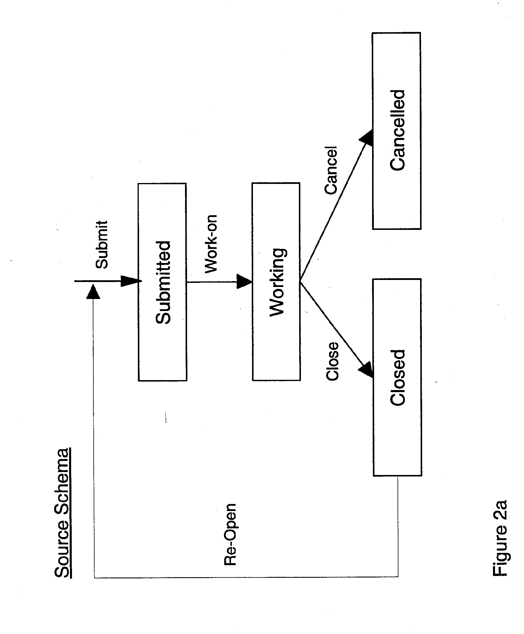
[0079]As shown in FIG. 3, a state (the redundant state) is chosen for deletion from the source database schema of FIG. 7a (step 100). In the example, the redundant state is R0. A resultant state is chosen to which to migrate records that are currently in the deleted or redundant state to (step 110). The resultant state must be one that exists in the target schema of FIG. 7c. In the example, R1 is the chosen resultant state.
[0080]Processing then proceeds to FIG. 4a. The system defines at step 120 a migration path array (mpa) which for a given row (x) has four attributes: a path identifier (pidx); a migration path (mpx); a first indicator (id1x); and a second indicator (id2x). The meaning of these attributes will become clear shortly.
[0081]The system sets up various variables (at step 130) for use during processing. These are as follows:
[0082]A current migration path (cmp) variable is set to the redundant state, R0;
[0083]x is the current row in the migration path array (mpa) being pro...
example 2
[0126]Dotted line 1 in FIG. 7a indicates the example in which an action does exist to migrate from the redundant state to a valid migration path:
[0127]The user chooses the same redundant state for deletion R0 and the same resultant state R1 at steps 100, 110.
[0128]Once again, a migration path array (mpa) is defined at step 120 and the same variables are initialised as before at step 130. The redundant state 140 is assigned to the migration path attribute in mpax, row 1, and the path id (pidx) is set to 1 also. List L0 is set to the list of all actions in the source schema which can advance from the redundant state to the resultant state or non-actionless state which also exists in the target schema (step 150). In this example, L0 includes action a2.1. This time around the test at step 160 is true. Step 200 of FIG. 4j dictates that all states which can be reached by all actions in list L0 should now be listed. In this example, the only state to be listed is S2. Thus state S2 is chose...
example 3
[0137]In this example, an action does not exist to advance from the redundant state, and the action selected does not lead to a valid migration path. This is indicated by dotted line 3 in FIG. 7b.
[0138]There are no actions in List L0 (step 160) and so processing proceeds to FIG. 4h, step 750. The second indicator in row 1 is not set and so all states in list L1 are presented (this list was initialised at step 130 of FIG. 4a). In this example, the user selects state S3 (step 770) and all actions which can result in S3 are presented—i.e. a3 (step 780). a3 is selected by the user at step 790 and the state and action are added to the current migration path and the mp attribute of row 1 (step 800). State S3 is not the resultant state (step 810) and so the first indicator in row x is set to incomplete at step 830:
Path IdMigration Path1st Indicator2nd Indicator1R0-a3-S3I
[0139]The system then advances row 1 of FIG. 4b (step 400). The path is incomplete and not invalid (step 410). The curre...
PUM
 Abstract
Description
Claims
Application Information
 - R&D
- Intellectual Property
- Life Sciences
- Materials
- Tech Scout
- Unparalleled Data Quality
- Higher Quality Content
- 60% Fewer Hallucinations
Browse by: Latest US Patents, China's latest patents, Technical Efficacy Thesaurus, Application Domain, Technology Topic, Popular Technical Reports.
© 2025 PatSnap. All rights reserved.Legal|Privacy policy|Modern Slavery Act Transparency Statement|Sitemap|About US| Contact US: help@patsnap.com


