Packing member for honeycomb structure and method for transporting honeycomb structure

a honeycomb and packaging member technology, applied in the field of packaging members for honeycomb structures and a method for transporting honeycomb structures, can solve the problems of harmful to the environment and the human body, vibration is applied to the honeycomb structure, and diesel engines have raised serious problems

Inactive Publication Date: 2009-04-30
IBIDEN CO LTD
View PDF98 Cites 100 Cited by
  • Summary
  • Abstract
  • Description
  • Claims
  • Application Information

AI Technical Summary

Problems solved by technology

In recent years, particulate matter (hereinafter, also referred to as PM) contained in exhaust gases discharged from internal combustion engines such as diesel engines have raised serious problems as contaminants harmful to the environment and the human body.
During processes, such as packaging and transporting of honeycomb structures and the like, however, an impact such as vibration is applied to the honeycomb structures; there exists a problem that the outer edge portion (in particular, the peripheral coat layer of the honeycomb structure) of the end face of each honeycomb structure is more susceptible to breakage such as chipping and cracking.

Method used


Image

  • Packing member for honeycomb structure and method for transporting honeycomb structure
  • Packing member for honeycomb structure and method for transporting honeycomb structure
  • Packing member for honeycomb structure and method for transporting honeycomb structure

Examples


first embodiment

[0096]Referring to FIGS. 4A, 4B, 4C, 5A and 5B, the following description will discuss a first embodiment that is one embodiment of the present invention.

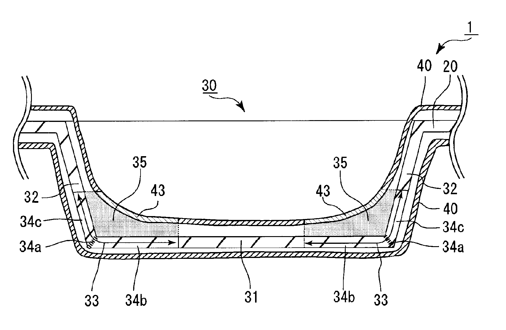
[0097]FIG. 4A is a perspective view that schematically shows one example of a packing member for honeycomb structures according to one embodiment of the present invention, and FIG. 4B is a plan view of the packing member for honeycomb structures shown in FIG. 4A. FIG. 4C is a cross-sectional view that schematically shows a cross section obtained by cutting the packing member for honeycomb structures shown in FIG. 4A in a direction perpendicular to the bottom face of a recessed portion of a holding member (A-A line cross-sectional view of FIGS. 4A and 4B).

[0098]Here, FIGS. 4A and 4B show a state in which one portion of a covering member is cut out so as to show the recessed portion of the holding member.

[0099]FIG. 5A is an exploded perspective view that schematically shows a mode in which honeycomb structures are being packed in the...

example 1

(1) Manufacturing of Holding Member

[0136]A plate member made of a polypropylene resin having a thickness of 1 mm was processed into a thickness of 0.2 mm, and a holding member having an outer shape of 580 mm in width×380 mm in length×40 mm in height, with five recessed portions, each having a size of 150 mm in diameter of the bottom face×155 mm in aperture diameter was formed on one face thereof.

(2) Covering

[0137]A covering member having a bag shape with one opening portion, which was made of a resin bag composed of polyethylene and had a size of 800 mm in length (depth)×382 mm in aperture diameter×0.04 mm in thickness, was prepared. Moreover, the holding member, manufactured in the process (1), was put into the resin bag from the opening portion. Then, the entire holding member was covered with the resin bag so that the holding member covered with the covering member was manufactured.

(3) Gas Filling

[0138]The resin bag was filled with air through the opening portion of the covering ...

examples 2 to 3

[0150]The same processes as those of Example 1 were carried out to manufacture a packing member for honeycomb structures, except that the material for the covering member was changed as shown in Table 1.


PUM

PropertyMeasurementUnit
thicknessaaaaaaaaaa
thicknessaaaaaaaaaa
diameteraaaaaaaaaa

Abstract

A packing member for a honeycomb structure includes a holding member and a covering member. The holding member includes a recessed portion having a bottom face and a side face. The holding member is configured to hold the honeycomb structure in the recessed portion. The recessed portion has a corner portion which includes a border portion between the bottom face and the side face. The covering member covers at least the recessed portion and is provided to form a gas layer between the covering member and the corner portion.

Description

CROSS-REFERENCE TO RELATED APPLICATIONS[0001]The present application claims priority under 35 U.S.C. § 119 to PCT Application No. PCT / JP2007 / 071238, filed Oct. 31, 2007, the contents of which are incorporated herein by reference in their entirety.BACKGROUND OF THE INVENTION[0002]1. Field of the Invention[0003]The present invention relates to a packing member for a honeycomb structure and a method for transporting a honeycomb structure.[0004]2. Discussion of the Background[0005]In recent years, particulate matter (hereinafter, also referred to as PM) contained in exhaust gases discharged from internal combustion engines such as diesel engines have raised serious problems as contaminants harmful to the environment and the human body.[0006]For this reason, various honeycomb structures, which are made of porous ceramics such as cordierite and silicon carbide, have been proposed as filters that capture PM in exhaust gases and purify the exhaust gases.[0007]During processes, such as packa...

Claims


Application Information

Patent Timeline
Patent Type & Authority Applications(United States)
IPC IPC(8): B65D81/113B32B3/00B32B1/08B65D81/02B32B1/02
CPCB65D5/5028B65D81/05B65D81/113Y10T428/24612Y10T428/1334Y10T428/13B65D2585/6882
Inventor OTSUKA, MUTSUOTELEKI, ANDRAS
Owner IBIDEN CO LTD
Why Eureka
Try Eureka