Notched Tie Plate Insulator

a technology of insulating tie plates and notched ends, which is applied in the direction of ballastways, roads, constructions, etc., can solve the problems of not being able to take the high rail traffic, failing prematurely, and being difficult to move the clip. , to achieve the effect of limited lateral movement of the clip

Inactive Publication Date: 2009-04-30
KOPPERS DELAWARE INC
View PDF32 Cites 32 Cited by
  • Summary
  • Abstract
  • Description
  • Claims
  • Application Information

AI Technical Summary

Benefits of technology

[0009]The present invention can also be a tie plate assembly for a railroad rail that includes a tie plate having a recessed area adapted to receive a railroad rail, a layer of electrically-insulating material covering the recessed area of the tie plate, a plurality of slots defined on the tie plate and a fastener passing through one of the slots for se

Problems solved by technology

Non-metallic insulating tie plates are typically very expensive because of the special high-performance materials needed to endure the high tensile and flexural forces acting on the railroad rail.
Also, prior art initially utilized unsupported

Method used


Image

  • Notched Tie Plate Insulator
  • Notched Tie Plate Insulator
  • Notched Tie Plate Insulator

Examples


second embodiment

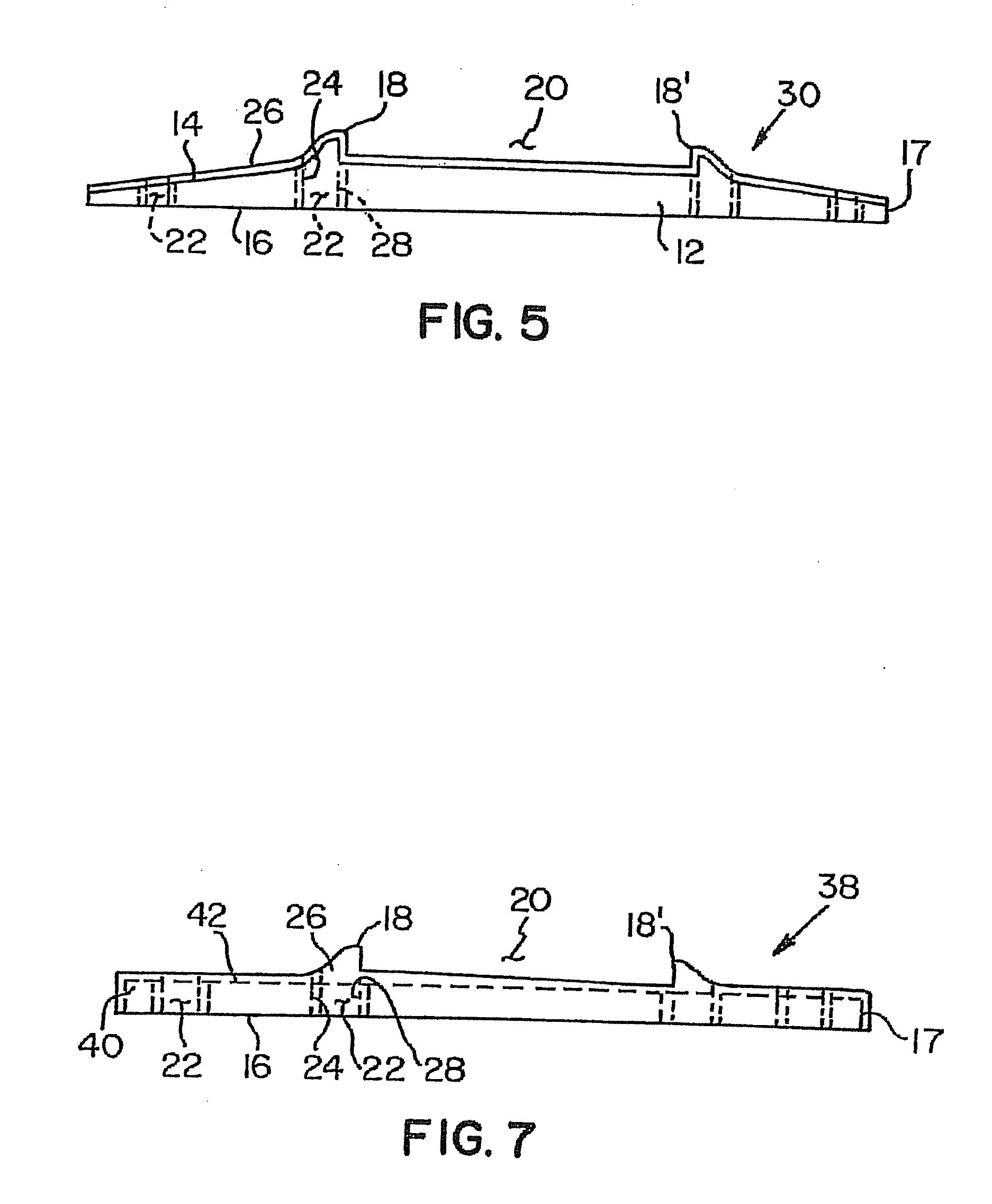
[0033]FIG. 5 shows a tie plate 30, which is similar to a tie plate 10 except for the below noted difference. Like reference numerals are used for like elements. In tie plate 30, only the first surface 14 of the base plate 12 is covered by a layer 26 of electrically-insulating material instead of the entire base plate 12 as in tie plate 10.

third embodiment

[0034]FIG. 6 shows a tie plate 34, which is similar to a tie plate 30 except for the below noted difference. Like reference numerals are used for like elements. In tie plate 34, only the recessed area 20 and the shoulder members 18, 18′ on the first surface 14 of the base plate 12 are covered by a layer 26 of electrically-insulating material instead of the entire first surface 14 as in tie plate 30. Optionally, the layer 26 may not include lips 19 and 19′ depending from legs A and B of the layer 26. Preferably, the layer 26 is made of UHMWPE or laminated fiberglass, but other insulating materials may be used.

fourth embodiment

[0035]FIG. 7 shows a tie plate 38, which is similar to a tie plate 30 except for the below noted difference. Like reference numerals are used for like elements. Tie plate 38 includes a rectangular-shaped base plate 40 having a planar first surface 42. The layer 26 of electrically-insulating material also covers the first surface 42 and the peripheral edges 17 of the base plate 40. The overall shape of the tie plate 38 is similar to tie plates 10, 30, and 34 except that the pair of longitudinal-extending shoulder members 18, 18′ are made of an electrically-insulating material.

[0036]FIG. 8 shows a tie plate assembly 50 for a railroad rail 56 made in accordance with the present invention, wherein like reference numerals are used for like elements. The tie plate assembly 50 includes an electrically-insulated tie plate 52 having a recessed area 54 adapted to receive the railroad rail 56, a plurality of slots 58, 58′ defined on the tie plate 52, and at least one fastener 60 passing throug...


PUM


Abstract

A notched tie plate insulator adapted to be received within a recessed area of a tie plate of a railroad rail system. The insulator includes a bottom plate having a first side and a second side and a pair of side plates attached to the bottom plate. Each side of the bottom plate defines a notch therein. The side plate includes a longitudinal extending body having an upper surface and a lower surface and defining a recess on the upper surface and a protrusion on the lower surface, wherein the protrusion of each of the side plates is received within the notches of the bottom plate.

Description

CROSS REFERENCE TO RELATED APPLICATION[0001]This application claims the benefit of U.S. Provisional Application No. 60 / 966,956, entitled “Notched Tie Plate Insulator”, filed on Aug. 31, 2007, which is hereby incorporated by reference.BACKGROUND OF THE INVENTION[0002]1. Field of the Invention[0003]The present invention relates to insulated tie plates and, more particularly, to a tie plate insulator for electrically isolating parts of a rail system from each other.[0004]2. Description of Related Art[0005]A rail system is generally divided into sections or blocks for detecting trains which permit more trains to travel on one stretch of track or railroad rails. Each section is electrically isolated from all other sections so that when no train is present, a high electrical resistance can be measured over the parallel railroad rails in that section. When a train enters the section, the train short circuits adjacent railroad rails and the electrical resistance drops, thus indicating that ...

Claims


Application Information

Patent Timeline
IPC IPC(8): E01B9/40
CPCE01B9/40E01B26/00E01B9/42
Inventor MOSPAN, JOHN W.URMSON, JR., W. THOMAS
Owner KOPPERS DELAWARE INC
Why Eureka
Try Eureka