Optical scanning device

Inactive Publication Date: 2009-04-30
KONINKLIJKE PHILIPS ELECTRONICS NV
View PDF7 Cites 0 Cited by
  • Summary
  • Abstract
  • Description
  • Claims
  • Application Information

AI Technical Summary

Benefits of technology

[0009]It is an object of the invention to provide an optical scanning device and a method for accurately and efficiently scanning record carriers using evanescent coupling by allowing a tilt misalignment between the optical scanning device and a record carrier to be detected and corrected for, especially to enable a tilt misalignment between the optical scanning device and a record carrier to be detected and corrected for during normal operation of the optical scanning device.

Problems solved by technology

For near-field systems using evanescent coupling to scan record carriers, a deviation from a desired level of tilt alignment has a detrimental effect on the quality and accuracy of data being written and / or read during scanning of the record carrier.
Near-field systems employing evanescent coupling have relatively small margins of mechanical tolerance, outside of which the efficiency of the evanescent coupling deteriorates.
A deviation from the desired level of tilt alignment exceeding these tolerance margins can cause this deterioration in the efficiency and therefore a detrimental effect on the data quality and accuracy.
Moreover, such a deviation will cause the SIL to make contact with the record carrier, possibly causing damage and / or failure of the system.

Method used


Image

  • Optical scanning device
  • Optical scanning device
  • Optical scanning device

Examples


Embodiment Construction

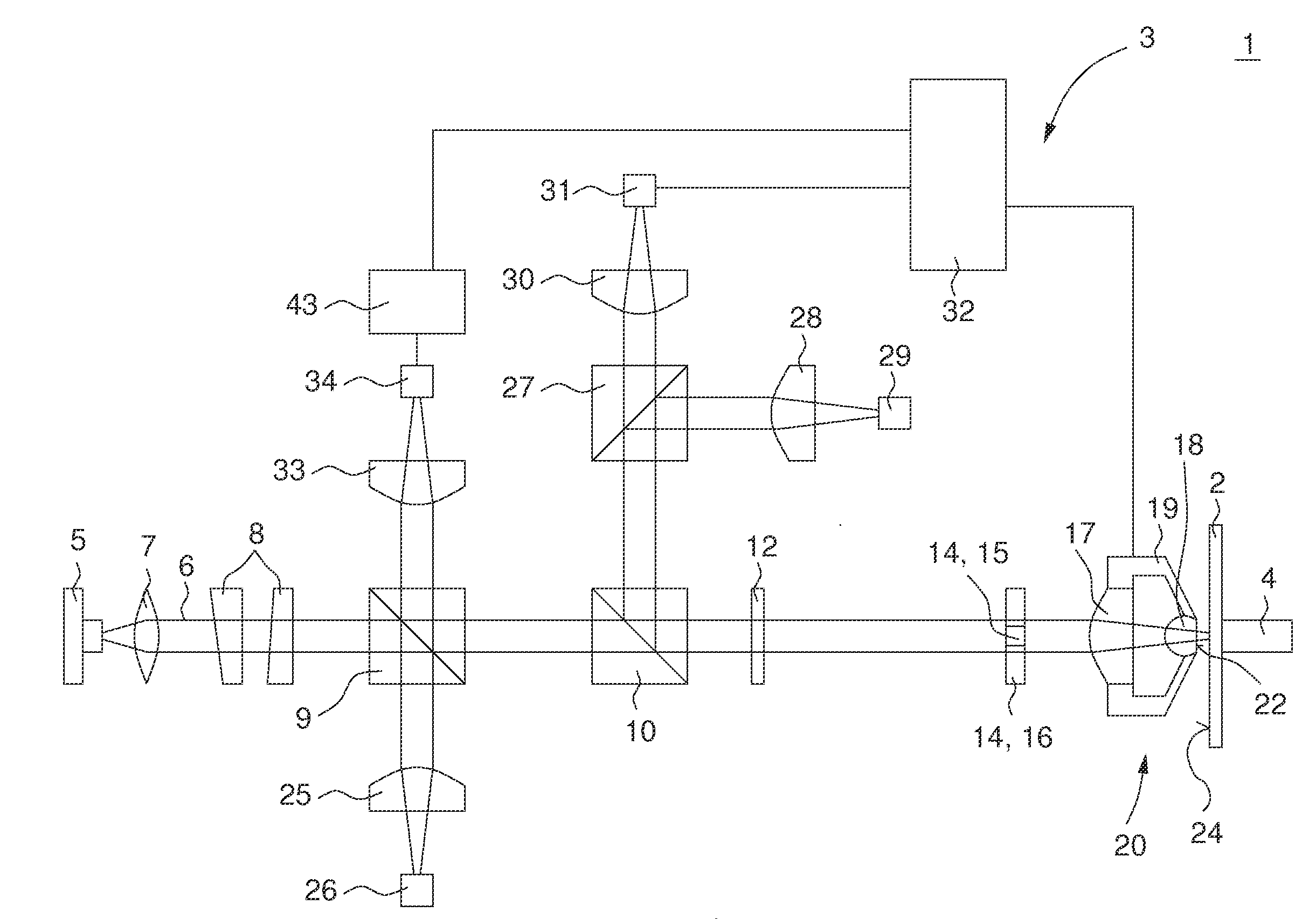
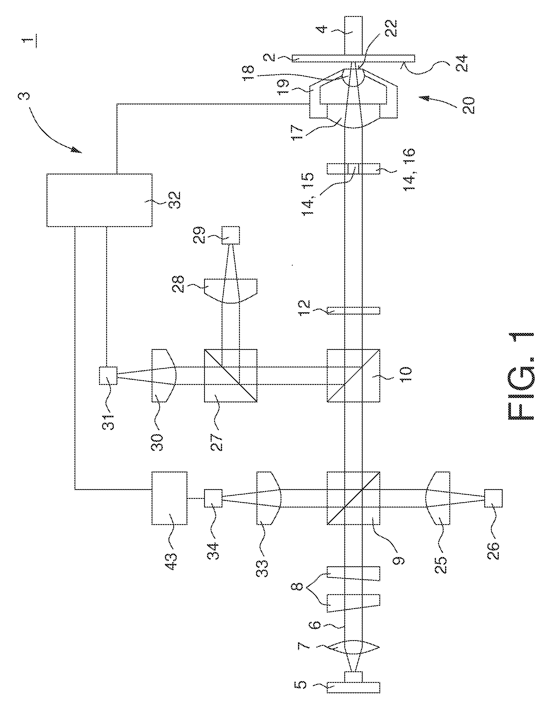
[0036]FIG. 1 shows a schematic illustration of an optical recording apparatus 1 for scanning a record carrier 2 in accordance with a preferred embodiment of the present invention. The optical recording apparatus 1 comprises an optical scanning device 3 and a mounting element 4, especially a rotating shaft 4, for rotating the record carrier 2. The optical recording apparatus 1 and the optical scanning device 3 are especially used in combination with a solid immersion lens for high-density optical scanning applications. But, the optical recording apparatus 1 and the optical scanning device 3 may also be used in other applications and in combination with other optical or non-optical reading and / or writing procedures.

[0037]The optical scanning device comprises a radiation source system 5 which is arranged to generate a radiation beam 6. In this embodiment the radiation source system 5 is a laser 5 and the radiation beam 6 is a laser beam 6 having a predetermined wavelength λ, for exampl...


PUM


Abstract

An optical scanning device (3) for scanning a record carrier (2) comprises an objective unit (20) and a diffraction element (14). The objective unit (20) is adapted to transmit an auxiliary radiation beam (21) towards the record carrier (2) in a defocused mode in addition to a main radiation beam (6) that is used for read-out and / or writing operations. The diffraction element (14) defines a measuring region (16) with respect to a spot (44) of the main radiation beam (6) so as to avoid an influence of the auxiliary radiation beam (21) on the main radiation beam (6) reflected. Hence, the performance of read-out and / or writing operations is increased.

Description

[0001]The present invention relates to an optical scanning device for scanning record carriers using evanescent coupling of radiation.BACKGROUND OF THE INVENTION[0002]In a particular type of high-density optical scanning device, a solid immersion lens (SIL) is used to focus a radiation beam to a scanning spot onto an information layer of a record carrier. A certain distance between the exit face of the SIL and the outer face of the record carrier, for example 25 nm, is desirable to allow evanescent coupling of the radiation beam from the SIL to the record carrier. Evanescent coupling may otherwise be referred to as frustrated total internal reflection (FTIR). Such systems are known as near-field systems, deriving their name from the near field formed by the evanescent wave at an exit face of the SIL. The optical scanning device may use blue semiconductor laser as radiation source that emits a radiation beam having a wavelength of approximately 405 nm.[0003]During scanning of the rec...

Claims


Application Information

Patent Timeline
IPC IPC(8): G11B7/00G11B7/12G11B7/135
CPCG11B7/0956G11B7/1387G11B7/122G02B26/10G11B7/1353G11B7/1374
Inventor ZIJP, FERRYVERSCHUREN, COEN ADRIANUS
Owner KONINKLIJKE PHILIPS ELECTRONICS NV
Why Eureka
Try Eureka