
Optical scanning device

a scanning device and optical scanning technology, applied in the field of optical scanning devices, can solve the problems of reducing the quality of the scanning spot, and the inability to accurately and efficiently scan the record carrier

Inactive Publication Date: 2009-11-03
KONINK PHILIPS ELECTRONICS NV
View PDF5 Cites 1 Cited by
  • Summary
  • Abstract
  • Description
  • Claims
  • Application Information

AI Technical Summary

Benefits of technology

[0009]It is an object of the invention to provide an optical scanning device for accurately and efficiently scanning record carriers using evanescent coupling by allowing a tilt misalignment between the optical scanning device and a record carrier to be detected and corrected for.
[0017]The tilt error signals can be used to correct the tilt misalignment such that an improved efficiency of evanescent coupling across the total exit face area may be achieved. The record carrier may therefore be scanned with a relatively high quality and level of accuracy. Additionally, the detection and correction of the tilt misalignment does not involve any writing of data on the disc. A tilt misalignment correction procedure is therefore relatively quick and does not necessarily require use of data capacity of the record carrier.
[0019]In some embodiments of the present invention, the radiation generated by the radiation source system is a radiation beam and the device is arranged to introduce defocus into the radiation beam such that the radiation beam is not focused onto the outer face of the record carrier, thereby increasing a diameter of the spot at the exit face.
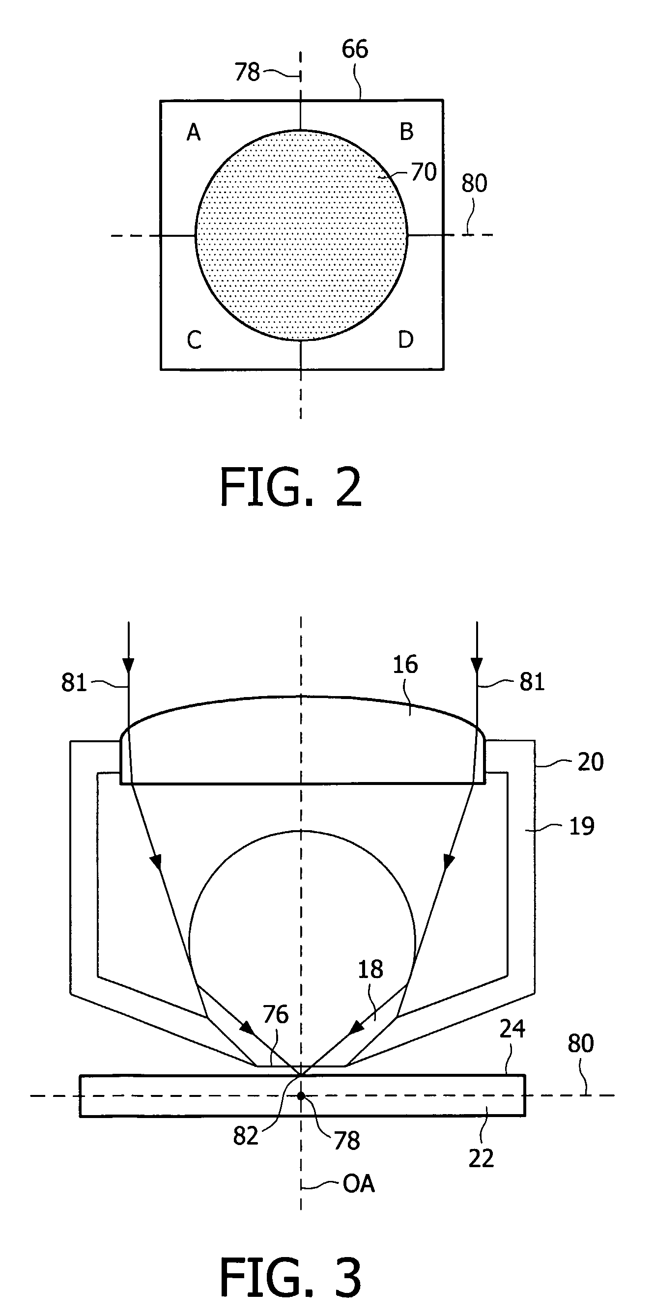
[0021]The spot of this radiation beam at the exit face has an increased diameter, so that a cross sectional area of the radiation beam covers at least one quarter of a total area of the exit face. This increased diameter results in an increase of the area of the first, second, third and fourth exit face areas. This allows a greater amount of information of the efficiency of the evanescent coupling across the exit face to be detected and consequently allows a more accurate adjustment of the tilt misalignment to be performed.
[0023]By producing a corrected tilt alignment during the start-up procedure and maintaining the corrected tilt alignment after start-up, the record carrier may be accurately scanned without needing to adjust a tilt misalignment during scanning of the record carrier after the start-up procedure.
[0025]By adjusting the tilt misalignment at different points across the record carrier, it is possible to accurately scan a record carrier having a changeable surface tilt, for example across a radius in the case of the record carrier being a disc. Such record carriers may have been manufactured to a poor level of quality, or may have deteriorated, for example by developing a warp, due to environmental conditions.

Problems solved by technology

With an increase away from a desired gap distance the coupling efficiency will tend to decrease and consequently a quality of the scanning spot will also decrease.
If the scanning function involves reading data from the record carrier, for example, this decrease in efficiency will result in a decrease in the quality of the data being read, possibly with the introduction of errors into the data signal.
In non near-field systems, such as compact disc (CD), digital versatile disc (DVD) or Blu-ray, it has been known that tilt misalignment of the record carrier with respect to an optical axis of an objective lens system can adversely affect quality of the scanning spot during writing to and reading from the information layer.
Changes in tilt misalignment may be attributed to an unevenness of a planarity of the record carrier.
This may be due to warping of the disc, possibly due to environmental factors such as high temperatures over time or to a low quality manufacturing process of the record carrier.
Alternatively, or in addition, tilt misalignment may be caused by poor clamping of the record carrier within the scanning device.
Use of a conventional tilt detector for detecting tilt misalignment of the record carrier would not provide a sufficient level of accuracy in a near-field system due to the very small tolerances involved, and further would require a high degree of alignment of the objective system with respect to the tilt detector.
Exceeding such small tolerances may lead to contact between the SIL and the record carrier, possibly damaging the SIL and / or the record carrier.
Use of an optimisation routine, similar to the known systems, for measuring and estimating tilt misalignment in a near-field system would not be practical.

Method used


Image

  • Optical scanning device
  • Optical scanning device
  • Optical scanning device

Examples


Embodiment Construction

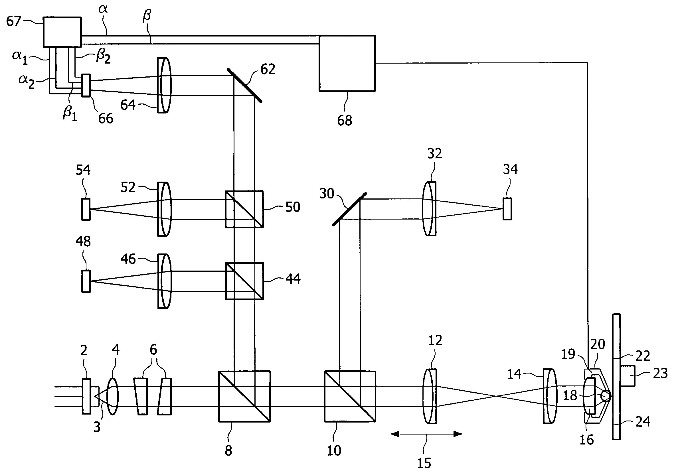
[0038]FIG. 1 shows schematically an optical scanning device for scanning a record carrier in accordance with an embodiment of the present invention.

[0039]The optical scanning device comprises a radiation source system which is arranged to generate a radiation beam. In this embodiment the radiation source system is a laser 2 and the radiation beam is a laser beam 3 having a predetermined wavelength λ, for example approximately 405 nm. During both a start-up procedure and a record carrier scanning procedure of the optical scanning device, the radiation beam 3 passing along an optical axis OA of the optical scanning device (not indicated) is collimated by a collimator lens 4 and its cross-sectional intensity distribution shaped by a beam shaper 6. The radiation beam 3 then passes through a non-polarising beam splitter 8, followed by a polarising beam splitter 10 and is then focused by a first focus adjustment lens 12 and a second focus adjustment lens 14. The focusing of the radiation ...


PUM

PropertyMeasurementUnit
wavelengthaaaaaaaaaa
gap sizeaaaaaaaaaa
frequencyaaaaaaaaaa

Abstract

An optical scanning device for scanning a record carrier (22), the record carrier has an outer face (24) and the optical scanning device comprises a radiation source system (2) arranged to generate a radiation beam; an objective system (20) having an exit face (76) and which is arranged between the radiation source system and the record carrier and provides for evanescent coupling of the radiation across a gap between the exit face of the objective system and the outer face of the record carrier; and a radiation detector arrangement for detecting radiation after interaction with the record carrier. The radiation detector arrangement is arranged to produce a tilt error signals (α, β) representing a tilt misalignment between the exit face of the objective system and the outer face of the record carrier. The radiation detector arrangement is arranged to produce the tilt error signal by detecting information in the radiation which is indicative of a variation in efficiency off the evanescent coupling across the exit face.

Description

FIELD OF THE INVENTION[0001]The present invention relates to an optical scanning device for scanning record carriers, in particular for scanning record carriers using evanescent coupling of radiation.BACKGROUND OF THE INVENTION[0002]In a particular type of high-density optical scanning device, a solid immersion lens (SIL) is used to focus a radiation beam to a scanning spot onto an information layer of a record carrier. A certain distance between the exit face of the SIL and the outer face of the record carrier, for example 25 nm, is desirable to allow evanescent coupling of the radiation beam from the SIL to the record carrier. Evanescent coupling may otherwise be referred to as frustrated total internal reflection (FTIR). Such systems are known as near-field systems, deriving their name from the near field formed by the evanescent wave at an exit face of the SIL. An exemplary optical scanning device may use a radiation source which is a blue laser and emits a radiation beam having...

Claims


Application Information

Patent Timeline
Patent Type & Authority Patents(United States)
IPC IPC(8): G11B7/00G11B7/135
CPCG11B7/0956G11B7/1387G11B2007/13727G11B7/085G11B7/09G11B7/095
Inventor VERSCHUREN, COEN ADRIANUSZIJP, FERRY
Owner KONINK PHILIPS ELECTRONICS NV
Learn More