Wireless communication apparatus and wireless communication method

a wireless communication and wireless communication technology, applied in multiplex communication, orthogonal multiplex, channel coding adaptation, etc., can solve the problem of significant degraded error correction performance and achieve the effect of maximum throughpu

Active Publication Date: 2009-04-30
PANASONIC INTELLECTUAL PROPERTY CORP OF AMERICA
View PDF7 Cites 46 Cited by
  • Summary
  • Abstract
  • Description
  • Claims
  • Application Information

AI Technical Summary

Benefits of technology

[0012]The radio communication apparatus of the present invention dividing a plurality of subcarriers forming a multicarrier signal into a plurality of resource blocks and performing adaptive control per resource block, the radio communication apparatus employs a configuration having: an encoding section that encodes all of the plurality of resource blocks at a same coding rate; a control section that controls a modulation scheme and a repetition factor per resource block; a modulating section that performs modulation per resource block using a controlled modulation scheme; and a repetition section that performs repetition per resource block using a controlled repetition factor.
[0013]According to the present invention, it is possible to yield maximum throughput and satisfy required received quality.

Problems solved by technology

Here, in error correcting encode such as turbo code, if the number of bits that can be transmitted per resource block decreases and the encoding block size becomes smaller, the error correcting performance is significantly degraded.

Method used


Image

  • Wireless communication apparatus and wireless communication method
  • Wireless communication apparatus and wireless communication method
  • Wireless communication apparatus and wireless communication method

Examples


embodiment 1

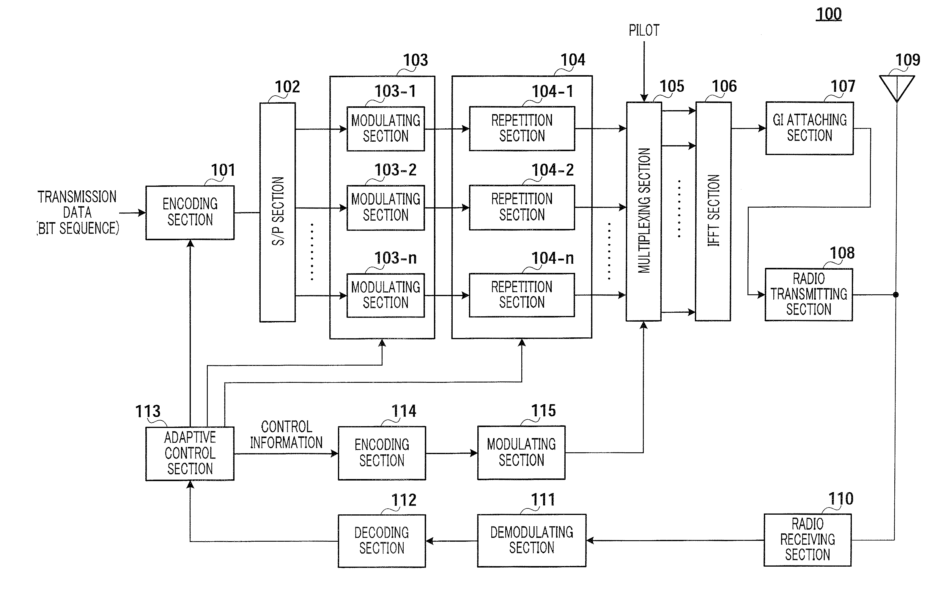
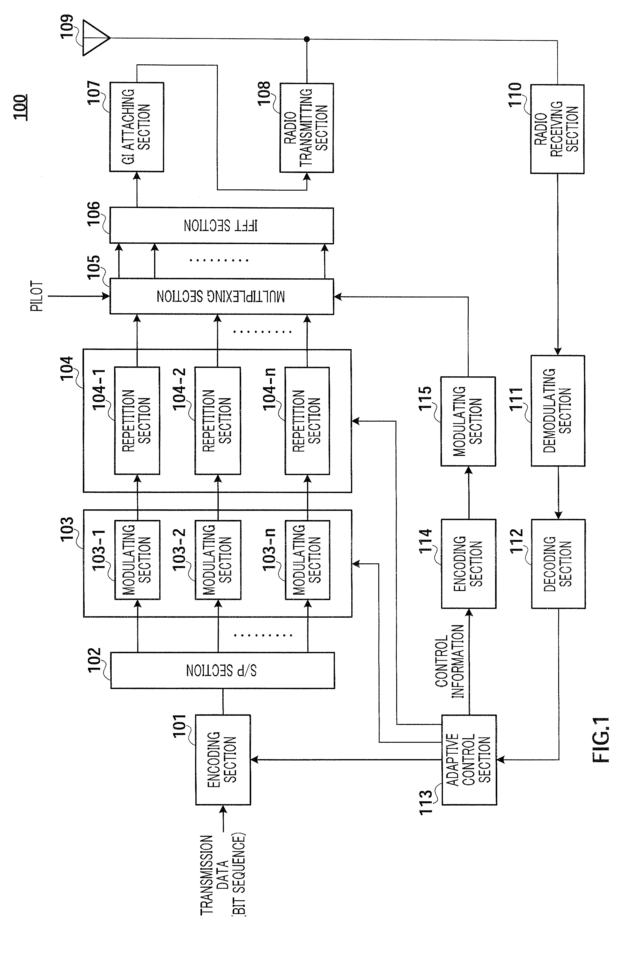
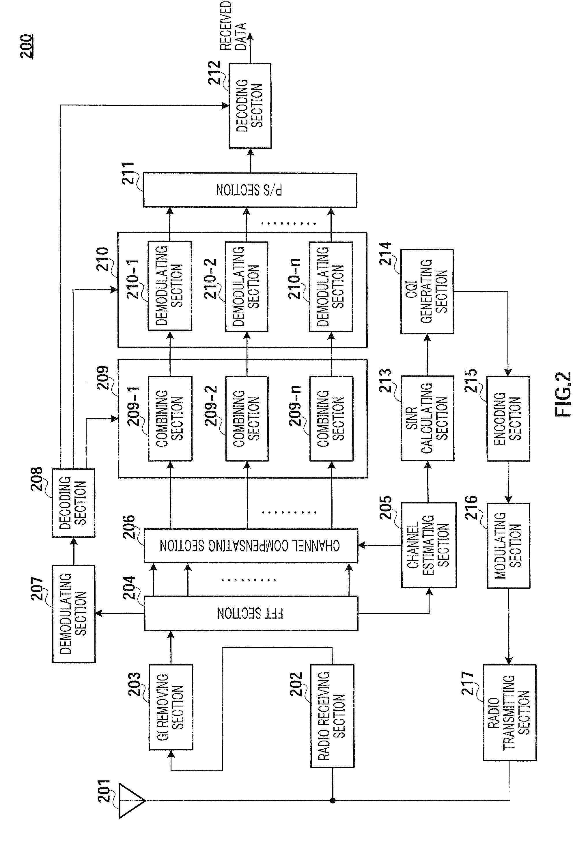
[0033]FIG. 1 illustrates the configuration of radio communication apparatus 100 on the transmitting side according to the present embodiment. FIG. 2 illustrates the configuration of radio communication apparatus 200 on the receiving side according to the present embodiment. Radio communication apparatus 100 divides a plurality of subcarriers forming an OFDM symbol, which is a multicarrier signal, into a plurality of resource blocks and performs adaptive control on a per resource block basis. Further, radio communication apparatus 200 receives the multicarrier signal, for which adaptive control is performed on a per resource block basis, and which is transmitted from radio communication apparatus 100.

[0034]In radio communication apparatus 100 shown in FIG. 1, encoding section 101 performs error correcting encoding on transmission data (bit sequence) at a coding rate that is common for all resource blocks inputted from adaptive control section 113, and outputs to S / P (serial / parallel)...

embodiment 2

[0064]According to the present embodiment, adaptive control is performed using the INR (Interference to Noise Ratio) in addition to the SINR.

[0065]FIG. 7 shows the configuration of radio communication apparatus 400 on the receiving side according to the present embodiment. In the figure, the same components as in Embodiment 1 (FIG. 2) are assigned the same numerals and explanations thereof will be omitted.

[0066]Channel estimating section 205 calculates a channel estimation value per subcarrier using the pilot symbol of each subcarrier. These channel estimation values are inputted to channel compensating section 206. Further, channel estimating section 205 detects the signal power value (S), interference power value (I) and noise power value (N) of the pilot symbol on a per subcarrier basis and outputs these values to SINR calculating section 213. Further, channel estimating section 205 outputs the interference power value (I) and noise power value (N) to INR calculating section 401....

embodiment 3

[0076]The present embodiment differs from Embodiment 1 in that bit repetition is performed instead of symbol repetition.

[0077]FIG. 11 illustrates the processing flow on the transmitting side according to the present embodiment. The processing flow of FIG. 11 differs from Embodiment 1 (FIG. 6) in that the order of performing the processing of adaptive modulation (ST 18-1 to 18-n) and repetitions (ST 19-1 to 19-n) is reverse, that is, adaptive modulation is performed after repetitions. Therefore, while symbol repetition is performed in ST 19-1 to 19-n in FIG. 6, bit repetition is performed in ST 19-1 to 19-n in FIG. 11.

[0078]FIG. 12 illustrates the configuration of radio communication apparatus 300 on the transmitting side according to the present embodiment Following the processing flow in FIG. 11, radio communication apparatus 300 employs a configuration having repetition section 104 before modulating section 103. The other components are the same as in Embodiment 1 (FIG. 1).

[0079]R...


PUM


Abstract

Provided is a wireless communication apparatus by which the maximum throughput can be obtained while satisfying required reception qualities in multicarrier communication. In the apparatus, a coding section (101) performs error correction coding to all of the plurality of resource blocks at a same coding rate, modulating sections (103-1 to 103-n) generate data symbols by modulating coding data for each of the resource blocks (1 to n), and repetition sections (104-1 to 104-n) repeat the data symbols inputted from the modulation section (103) for each of the resource blocks (1 to n) to generate a plurality of same data symbols. Namely, while the coding rate is same in all of the resource blocks, modulation system and the number of repetitions differ by resource block.

Description

TECHNICAL FIELD [0001]The present invention relates to a radio communication apparatus and a radio communication method.BACKGROUND ART [0002]In recent years, in radio communication, specifically, in mobile communication, various data such as image and data in addition to voice are targets for information transmission. Requests for high-speed transmission are anticipated to increase further in the future, and, to perform high-speed transmission, radio transmission techniques of using limited frequency resources efficiently and realizing high transmission efficiency are required.[0003]One of techniques capable of responding to such requests is orthogonal frequency division multiplexing (OFDM). It is known that OFDM is a multicarrier transmission technique that transmits data in parallel using a number of subcarriers, has features including high frequency efficiency and reduced inter-symbol interference under the multi-path environment, and is effective to improve transmission efficien...

Claims


Application Information

Patent Timeline
Patent Type & Authority Applications(United States)
IPC IPC(8): H04J3/16
CPCH04L1/0003H04L1/0009H04L1/0026H04L27/2602H04L1/08H04L1/1812H04L1/0028
Inventor KURI, KENICHINISHIO, AKIHIKOIMAMURA, DAICHIMIYOSHI, KENICHIARAMAKI, TAKASHIHIRAMATSU, KATSUHIKO
Owner PANASONIC INTELLECTUAL PROPERTY CORP OF AMERICA
Why Eureka
Try Eureka