Method for analysis of pressure response in underground formations

a pressure response and underground formation technology, applied in the field of methods for analysing the pressure response in an underground formation, can solve the problems of mud filtrate invasion and significant changes, environmental and cost considerations that do not allow the use of these techniques, and the difficulty in interpretation of pressure data acquired in this dynamic environmen

Active Publication Date: 2009-05-07
SCHLUMBERGER TECH CORP
View PDF11 Cites 17 Cited by
  • Summary
  • Abstract
  • Description
  • Claims
  • Application Information

AI Technical Summary

Problems solved by technology

While these can be excellent ways to meet test objectives, environmental and cost considerations do not allow use these techniques at all times. Wireline and LWD tools have been developed to make probe-based formation pressure measurements to address this issue.
However, interpretation of the pressure da

Method used


Image

  • Method for analysis of pressure response in underground formations
  • Method for analysis of pressure response in underground formations
  • Method for analysis of pressure response in underground formations

Examples


case 1.0

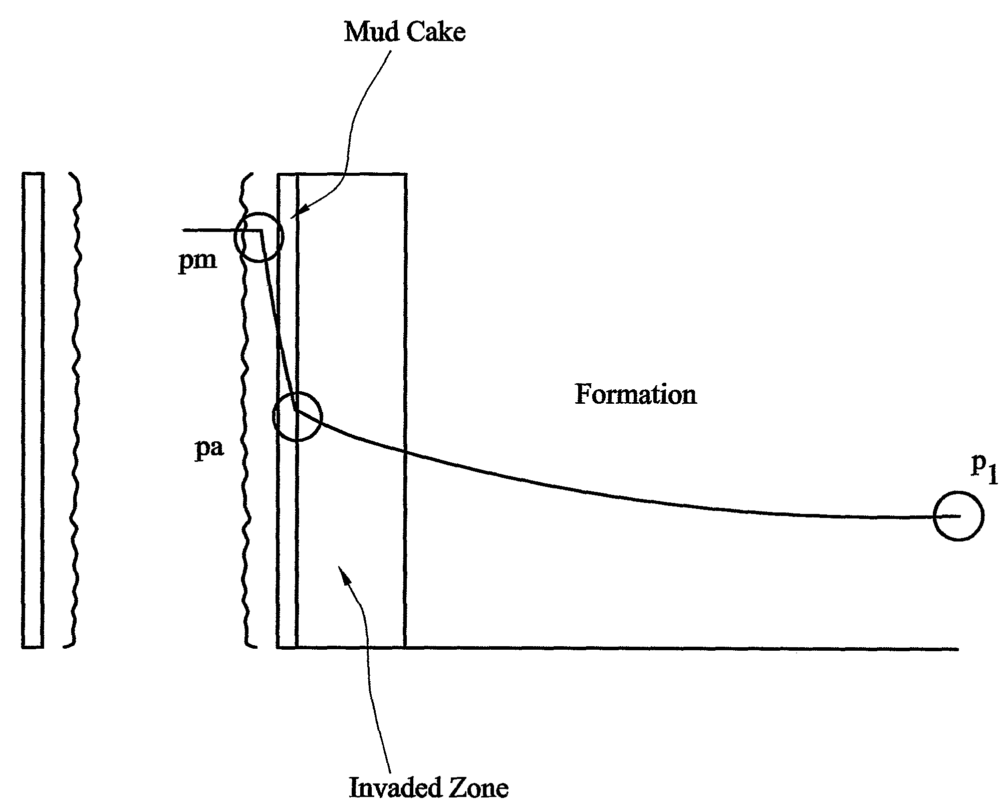
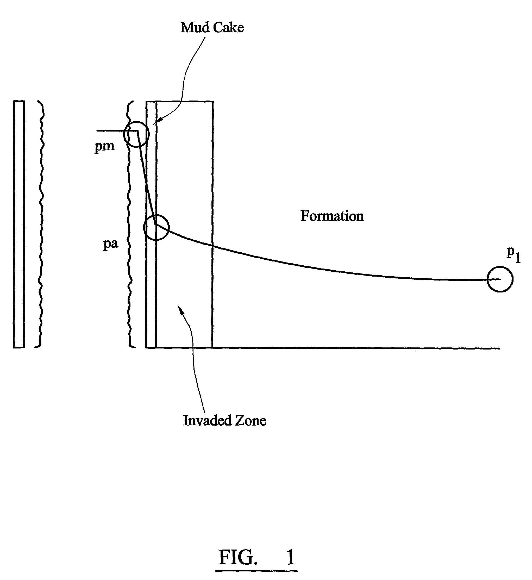
[0057] The medium is bounded by the cylinder r=a and extends to ∞ in the direction of r positive and

(-∞<z<∞)·∂p(a,θ,z,t)∂r=-(μk)aqM

The initial pressure situation is:

p(r,θ,z,t0)=(pa−pI)e−β(r−α)+pI; p(a,θ,z,t0)=pa

A continuous source at [a, 0, z0] is introduced and the resulting pressure disturbance left to diffuse through a semi-infinite homogeneous porous medium.

[0058]The solution in Laplace space is given by

p_(a,0,z,s)=2q(s)-st0π3φcta2ηz∑m=0∞∋m∫0∞-z-z0ηrξ2+sηzξ(ηrξ2+s){JM′2(ξa)+Ym′2(ξa)}ξ++4ηrπ2a(μk)MqM(s)∫0∞1ξ(ηrξ2+s){J0′2(ξa)+Y0′2(ξa)}ξ++2(pa-pI)βαπa∫0∞V0(ξa)(ηrξ2+s){J0′2(ξa)+Y0′2(ξa)}ξ+pIs(2)

[0059]and in real time

p_(a,0,z,t)=2U(t-t0)π3φcta2πηz∑m=0∞∋m∫0∞∫0t-t0q(t-t0-τ)-ηrξ2τ-(z-z0)24ηzτξτ{Jm′2(ξa)+Ym′2(ξa)}τξ++4ηrπ2a(μk)M(s)∫0∞∫0tqM(t-τ)-ηrξ2τξ{J0′2(ξa)+Y0′2(ξa)}τξ++2(pa-pI)βαπa∫0∞V0(ξa)-ηrξ2τ{J0′2(ξa)+Y0′2(ξa)}ξ+pI(3)

[0060]For constant q equation (3) reduces to

p_(a,0,z,t)=U(t-t0)qπ3φcta2πηrηz∑m=0∞∋m∫0∞-ξ(z-z0)ηrηzξ2{Jm′2(ξa)+Ym′2(ξa)}××{2-2ξ(z-z0)ηrηzerfc(ξηr(t-t0)+(z-z0)2...

case 2.0

[0062] The medium is bounded by the cylinder r=a and extends to ∞ in the direction of r positive and

(0<z<h)·∂p(a,θ,z,t)∂r=-(μk)aqM

The initial pressure situation is

p(r,θ,z,t0)=(pa−pI)e−β(r−a)+pI; p(a,θ,z,t0)=pa

A continuous source at [a, 0, z0] is introduced and the resulting pressure disturbance left to diffuse through a semi-infinite homogeneous porous medium.

[0063]The solution in Laplace space is given by

p_(a,0,z,s)=4q(s)-st0π3ha2φct∑m=0∞∋m∑n=0∞∋ncos(nπz0h)cos(nπzh)××∫0∞1ξ(ηrξ2+ηz(nπh)2+s){Jm′2(ξa)+Ym′2(ξa)}ξ++4π2a(μk)MqM(s)∫0∞1ξ(ηrξ2+s){J0′2(ξa)+Y0′2(ξa)}ξ++2(pa-pI)βαπa∫0∞V0(ξa)(ηrξ2+s){J0′2(ξa)+Y0′2(ξa)}ξ+pIs(5)

[0064]and in real time

p_(a,0,z,t)=U(t-t0)π3ha2φct∑m=0∞∋m∫0∞1ξ{Jm′2(ξa)+Ym′2(ξa)}∫0t-t0q(t-t0-τ)××[Θ3{π(z-z0)2h,-(πh)2ηzτ}+Θ3(π(z+z0)2h,-(πh)2ηzτ}]-ηrξ2ττξ++4π2a(μk)M∫0∞∫0tqM(t-τ)-ηrξ2τξ{J0′2(ξa)+Y0′2(ξa)}τξ++2(pa-pI)βαπa∫0∞V0(ξa)-ηrξ2τ{J0′2(ξa)+Y0′2(ξa)}ξ+pI(6)

[0065]For constant q equation (6) reduces to

p_(a,0,z,t)=U(t-t0)qπ3ha2φct∑m=0∞∋m∫0∞1ξ{Jm′2(ξa)+Ym′2(ξa)}∫0t-...


PUM


Abstract

A method of analysing a reservoir pressure in an underground formation surrounding a well, comprising: determining the permeability of mud cake on the wall of the well in the region in which the pressure measurement is made; determining the thickness of mud cake on the well of the well in the region in which the pressure measurement is made; determining the hydrostatic pressure in the well in the region in which the pressure measurement is made; measuring the formation pressure at the wall of the well; calculating a pressure decay index from the mud cake permeability and thickness, the hydrostatic pressure and the measured pressure; and using the pressure decay index to analyse the measured pressure to derive the reservoir pressure.

Description

TECHNICAL FIELD[0001]This invention relates to methods for analysing the pressure response in an underground formation, such as might be measured from a borehole passing through the formation. In particular, the methods apply to such methods for use when the formation pressure is influenced by the supercharging effect.BACKGROUND ART[0002]Formation pressure measurements made from wells play an important role in the management of reservoirs of underground fluids such as oil and gas. Because of their dynamic nature formation pressure measurements provide essential information on well productivity and dynamic reservoir description both in exploration and exploitation scenarios. Static pressure data can be used to compute formation fluid density and contacts. This can be important to determine reserves. Pressure transient data on the other hand can be important for estimating permeability and heterogeneity and average reservoir pressure.[0003]Traditionally, pressure transient testing has...

Claims


Application Information

Patent Timeline
IPC IPC(8): E21B47/06
CPCE21B47/06
Inventor THAMBYNAYAGAM, RAJ KUMAR MICHAELSPATH, JEFFREYBANERJEE, RAJWHITE, DAVID BRIANGOODE, PETER ALLAN
Owner SCHLUMBERGER TECH CORP
Why Eureka
Try Eureka