Nail Pulling Device

Inactive Publication Date: 2009-05-07
METZ SHANE W
View PDF5 Cites 6 Cited by
  • Summary
  • Abstract
  • Description
  • Claims
  • Application Information

AI Technical Summary

Benefits of technology

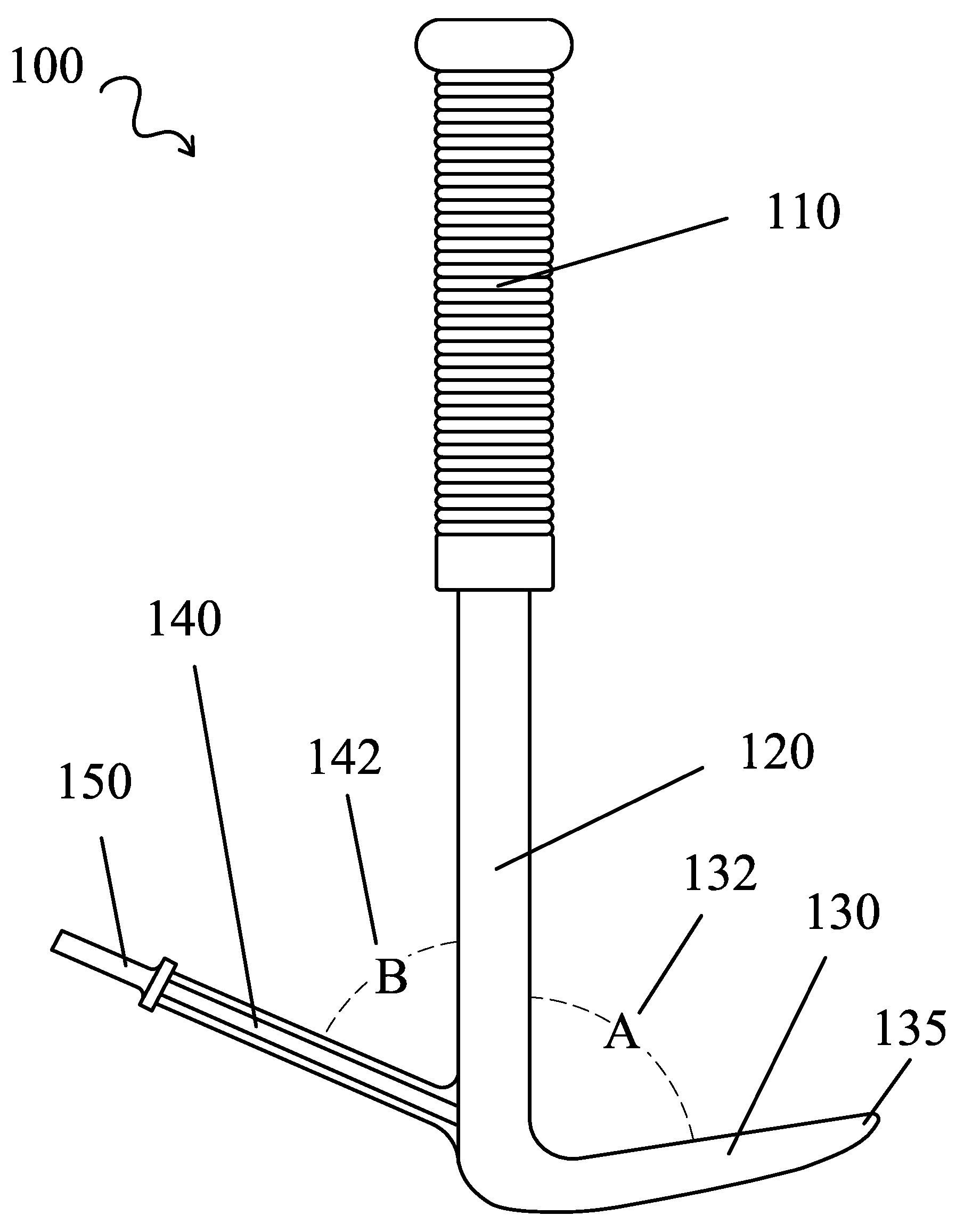
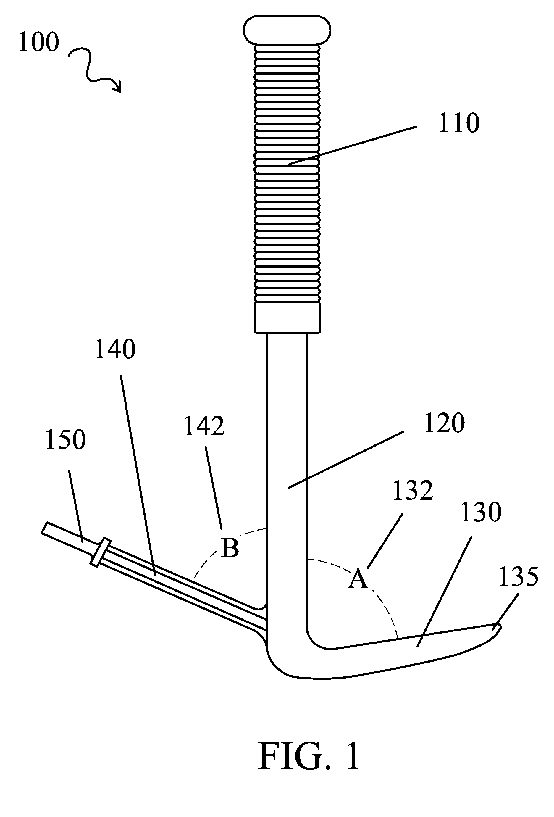
[0004]A nail removing device comprises a handle portion connecting a claw portion distally disposed therein and a shank attachment shaft disposed on an opposite side of the claw portion. The shank attachment shaft fits in a standard pneumatic tool such as an air chisel or hammer is angled to provide vibratory and impact action to the claw portion. In use the claw portion is placed next to the nail to be remov

Problems solved by technology

Sometimes, especially when working with older structures, the heads of the nails become embedded in the surface making the removal process laborious and difficult.
Many devic

Method used


Image

  • Nail Pulling Device
  • Nail Pulling Device
  • Nail Pulling Device

Examples


Example

[0016]In the following detailed description of the invention, reference is made to the drawings in which reference numerals refer to like elements, and which are intended to show by way of illustration specific embodiments in which the invention may be practiced. It is understood that other embodiments may be utilized and that structural changes may be made without departing from the scope and spirit of the invention.

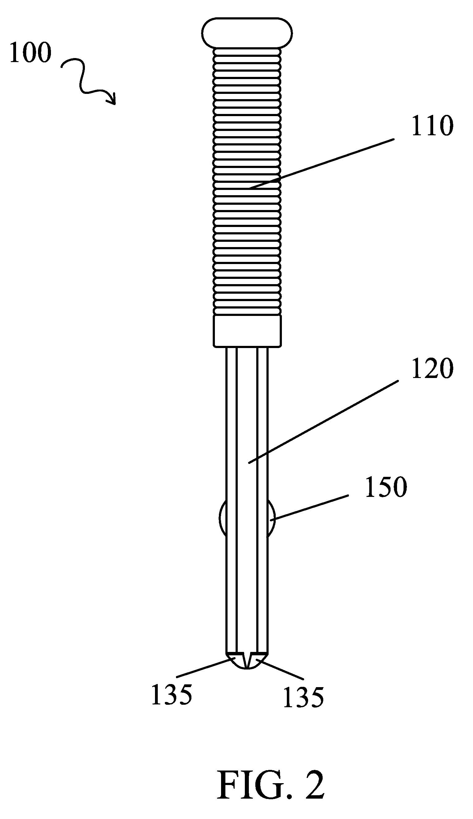
[0017]Referring to FIGS. 1, 2 and 7, a pneumatic nail pulling device 100 has a handle portion 110 which is made of an ergonomically friendly material such as rubber or plastic to cushion the grip and allow a user to hold device 100 without slipping. A shaft portion 120 is provided to allow leverage to be applied to a nail 160 by rotating around a claw portion 130. Claw portion 130 is disposed at an angle A 132 to shaft portion 120. Angle A 132 is generally between 90 degrees and 70 degrees, although other angles would be acceptable as long as a user applying a force to ...


PUM


Abstract

A nail removing device comprises a handle portion connecting a claw portion distally disposed therein and a shank attachment shaft disposed on an opposite side of the claw portion. The shank attachment shaft fits in a standard pneumatic tool such as an air chisel or hammer is angled to provide vibratory and impact action to the claw portion. In use the claw portion is placed next to the nail to be removed and the air tool is activated. Pressure is applied generally parallel to the surface of the material holding the nail and the combination of the action of the air tool and the leverage provided by rotating the handle portion allows the user to easily and quickly remove the nail from the material with minimal effort. Other embodiments include hydraulic or mechanical impact source in place of a pneumatic one.

Description

RELATED APPLICATIONS[0001]This application claims priority and herein incorporates by reference U.S. provisional patent application 60 / 983,288, filed Oct. 29, 2007.BACKGROUND OF THE INVENTION[0002]As soon as builders put together the first structure, someone had to take it apart. Nails appear at least as early as the Roman times and greatly advanced the art of putting together wooden structures. Nails were originally made by hand by blacksmiths and generally included a head portion which could be used to remove them at a later time by applying upward pressure. Of course now almost all nails are made by machine, but most still include a head portion to facilitate their holding power and to aid in their removal.[0003]To remove a nail from a material, a lever, such as a crow bar or hammer claw, is generally applied under the head of the nail and then and upward pressure is generated as the crow bar or claw is rotated around its fulcrum point to force the nail from the material. Sometim...

Claims


Application Information

Patent Timeline
IPC IPC(8): B25C11/00
CPCB25C11/00
Inventor METZ, SHANE W.
Owner METZ SHANE W
Why Eureka
Try Eureka