Ammunition supply system

Inactive Publication Date: 2009-05-14
RHEINMETALL LANDSYST
View PDF56 Cites 14 Cited by
  • Summary
  • Abstract
  • Description
  • Claims
  • Application Information

AI Technical Summary

Benefits of technology

[0011]In accordance with another aspect of the invention, the components usually disposed in the turret, but which do not need to be within the direct reach of the operator, are likewise placed on the outside of the turret between the protected cell and, if present, the protective casing. In this way, protection of these components is guaranteed by the protective casing disposed around the ammunition without using the protective cell to protect these components.
[0012]Moreover, by dividing-up of the protection of different components of the turret, an advantage is achieved in that different protection combinations ar

Problems solved by technology

However, large turrets have the disadvantage that they themselves are heavy and must be arm

Method used


Image

  • Ammunition supply system
  • Ammunition supply system
  • Ammunition supply system

Examples


Embodiment Construction

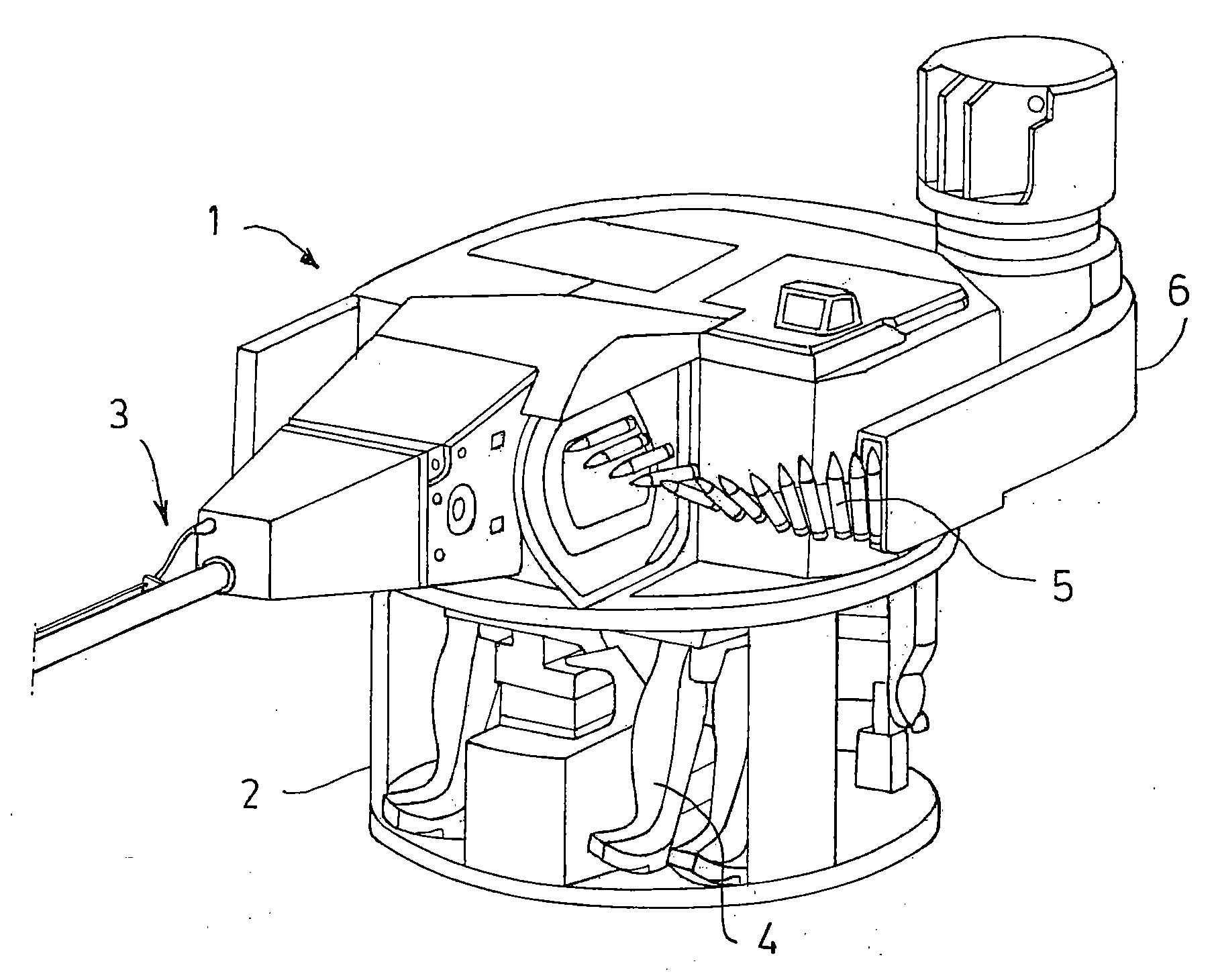
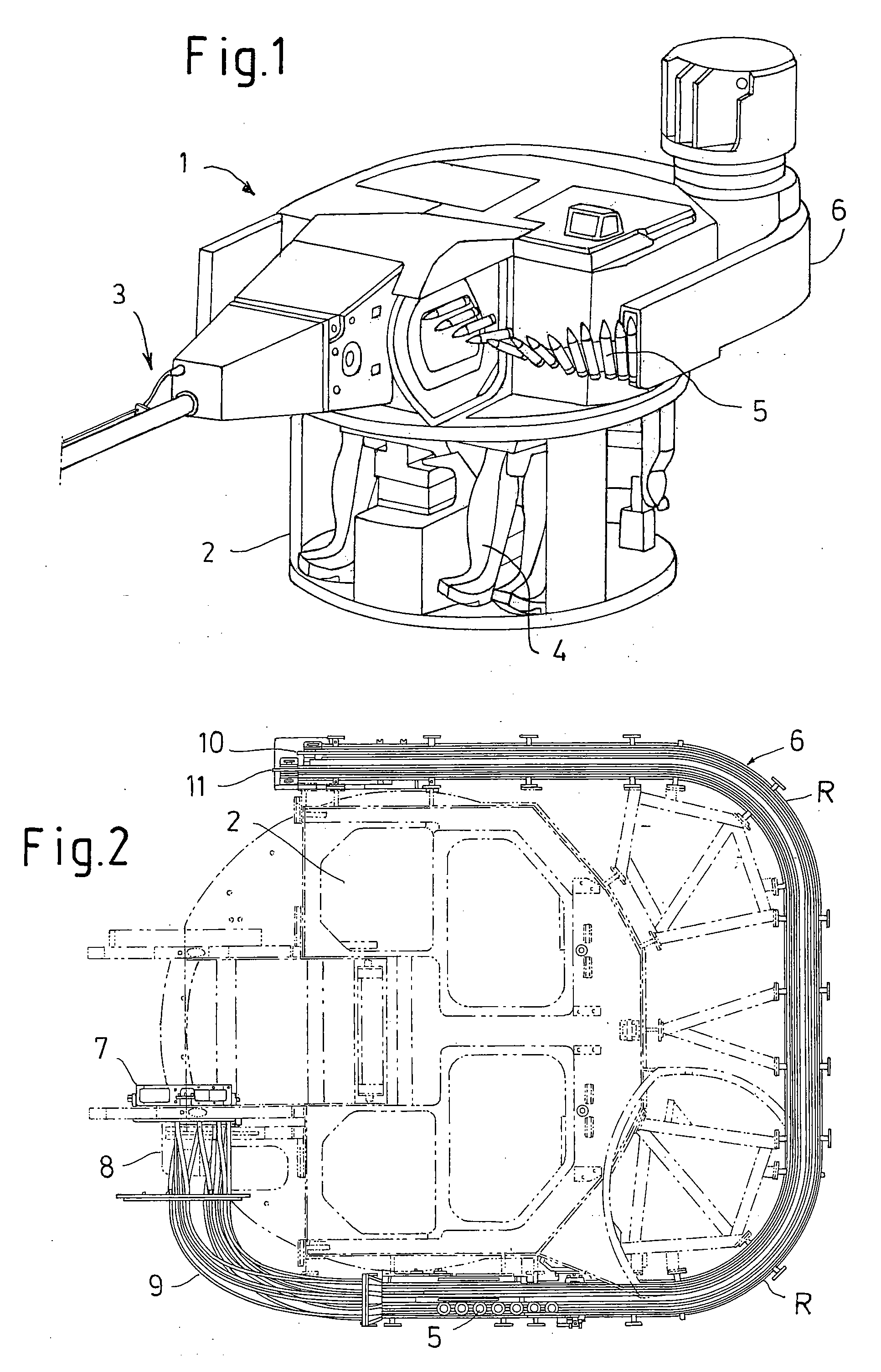
[0024]FIG. 1 shows a turret 1 with a protected cell 2, a weapon system 3, as well as indicated operators 4. Two types of ammunition 5 are fed laterally to the weapon 3. As a rule, there are at least two different types of ammunition that may be fed into the weapon 3. The ammunition 5 is fed to the weapon 3 from an ammunition supply system 6 rotating around the turret 1. The ammunition feed to the weapon takes place in a preferred embodiment by means of a support 7, a torsion apparatus 8, and a manifold 9, which are functionally connected to the ammunition supply system 6 (See FIG. 2).

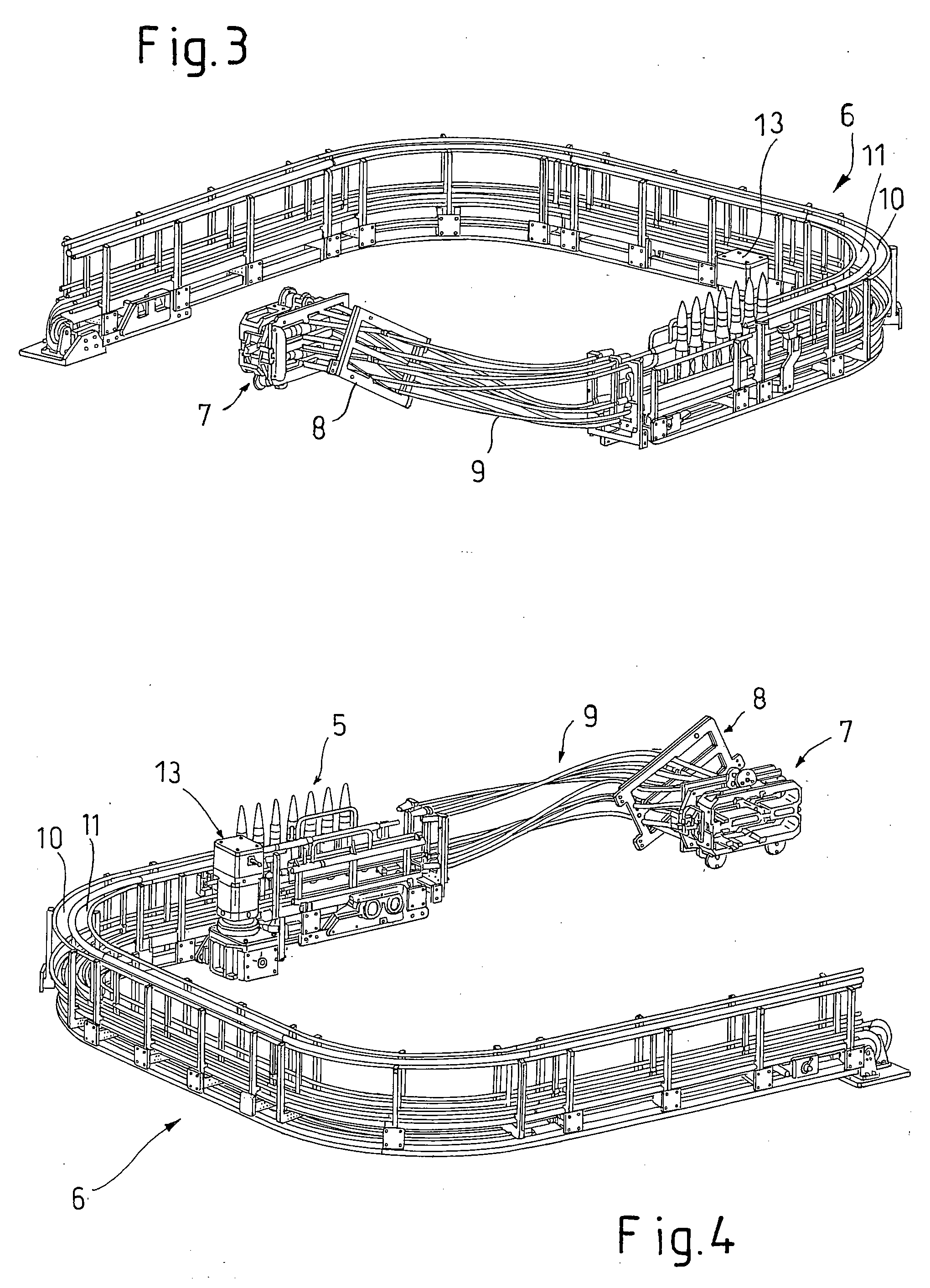
[0025]FIG. 2 shows the turret 1 with the rotating ammunition supply system 6, which is shown in more detail in FIGS. 3 and 4. The ammunition supply system 6 has two ammunition channels 10, 11, in which different types of ammunition are deposited. The transport to the manifold 9 takes place in the preferred embodiment with the aid of a rotating chain 12. The chain 12 is moved by means of an electric driv...


PUM


Abstract

In order avoid ammunition feed from within a protective cell of a turret (1) or an ammunition magazine, a type of ammunition supply system (6) is disposed around the entire or partial circumference of the turret (1). The ammunition supply system (6) has at least one ammunition channel (10, 11) filled with ammunition (5), whereby a drive (13) is incorporated for the transport of the ammunition (5), if the weapon (3) is not designed to pull the ammunition (5) by itself. In this case, an endless chain (12) works together with the drive (13), wherein the endless chain is movable in two axes. This endless chain enables transport of the ammunition (5) around the radii (R) of the turret (1).

Description

[0001]This application claims priority from German Patent Application No. 10 2007 041 294.2, filed Aug. 31, 2007, and on U.S. Provisional Patent Application No. 60 / 986,144, filed Nov. 7, 2007, and the entire disclosures of both documents are incorporated herein by reference.FIELD OF THE INVENTION[0002]The invention relates to a type of ammunition supply system that replaces a conventional ammunition magazine as a rotating ammunition feed around the turret.BACKGROUND OF THE INVENTION[0003]Ammunition magazines, or the like, for the acceptance of ammunition, wherein the magazines are accommodated in the vicinity of the turret or in the turret itself, are known. Thus, DE 195 26 664 A1 discloses a turret for a tank that is provided with a weapon and a magazine. The mounting of an ammunition magazine laterally on a gun mount is shown in DE 101 60 216 C1. An ammunition magazine that, in practice, is preferably arranged behind the turret is described in more detail in DE 10 2004 031 773 B3....

Claims


Application Information

Patent Timeline
IPC IPC(8): F41A9/29F41H5/20
CPCF41A5/20F41A9/04F41H7/04F41A9/76F41A9/37F41A9/57
Inventor DILLER, ARMINKRAUS, JOCHENSAULE, HANS
Owner RHEINMETALL LANDSYST
Why Eureka
Try Eureka