Fluidic Adaptive Lens Systems with Pumping Systems

a technology of adaptive lens and pumping system, applied in the field of optic lenses, can solve the problems of inability to mass produce at low cost, disadvantageous solid material lenses, and inability to meet the needs of mass production, and achieve the effect of less weight or bulkiness, and rapid

Inactive Publication Date: 2009-05-21
RGT UNIV OF CALIFORNIA +1
View PDF18 Cites 59 Cited by
  • Summary
  • Abstract
  • Description
  • Claims
  • Application Information

AI Technical Summary

Benefits of technology

[0009]The present inventors have recognized the desirability of providing improved devices for implementing / operating fluidic adaptive lenses. More particularly, the present inventors have recognized the desirability of providing improved fluid control or “pumping” devices that allow for fluid to be moved into or out of (and / or fluid pressure to be varied within) lens cavities of fluidic adaptive lenses, so as to achieve changes in the lens properties (e.g., changes in the focal length of the fluidic adaptive lens) by modifying the position of a flexible membrane. The present inventors have further developed a variety of different embodiments of pumping systems and tunable lens systems employing such pumping systems. At least some pumping systems in accordance with at least some embodiments of the present invention are capable of more precisely and rapidly effecting changes in lens properties than is possible using conventional pumping systems, and / or are of less weight or bulkiness (even to the point of being comparable in weight and size to the lenses themselves) than conventional systems.

Problems solved by technology

Although lenses made from solid materials generally maintain their optical properties over time, the use of such lenses also has numerous disadvantages, as discussed in PCT patent application no PCTUS05 / 10948 filed on Mar. 31, 2005 and U.S. provisional patent application No. 60 / 558,293 filed on Mar. 31, 2004, both entitled “Fluidic Adaptive Lens”, and both of which are incorporated by reference herein.
To begin with, solid material lenses are disadvantageous insofar as such lenses are typically difficult and costly to manufacture, and nearly impossible to mass produce at low cost.
Further, solid material lenses are disadvantageous insofar as such lenses have magnification powers (and other characteristics) that are fixed at the time of fabrication.
Because such lenses have fixed magnification powers (and other characteristics), such lenses by their nature only are able to meet the needs of their users (human or mechanical) for limited periods of time or under certain circumstances.
The use of combination-type lens devices such as bifocals, while helpful in certain regards, only partially alleviates these problems.
However, the use of such devices is disadvantageous in certain regards.
To begin with, the mechanical nature of such pumps (whether they are peristaltic, rotary, or injection-type pumps) increases their chance of failure.
Additionally, because such mechanical pumps employ separate actuation elements that rely on relatively large volumetric strokes (e.g., several micrometers or greater) at relatively low frequencies (e.g., 100 Hz or less), these pumps result in rather inaccurate lens tuning, and relatively slow fluidic response and associated slow lens tuning time.
Further, the use of such mechanical pumps results in a relatively bulky, expensive system assembly.
Similarly, the use of macroscopic fluidic connectors to connect the pumps to the lenses increases the overall size of, and the complexity and expense of fabricating, the combined lens and pump system.

Method used


Image

  • Fluidic Adaptive Lens Systems with Pumping Systems
  • Fluidic Adaptive Lens Systems with Pumping Systems
  • Fluidic Adaptive Lens Systems with Pumping Systems

Examples


Embodiment Construction

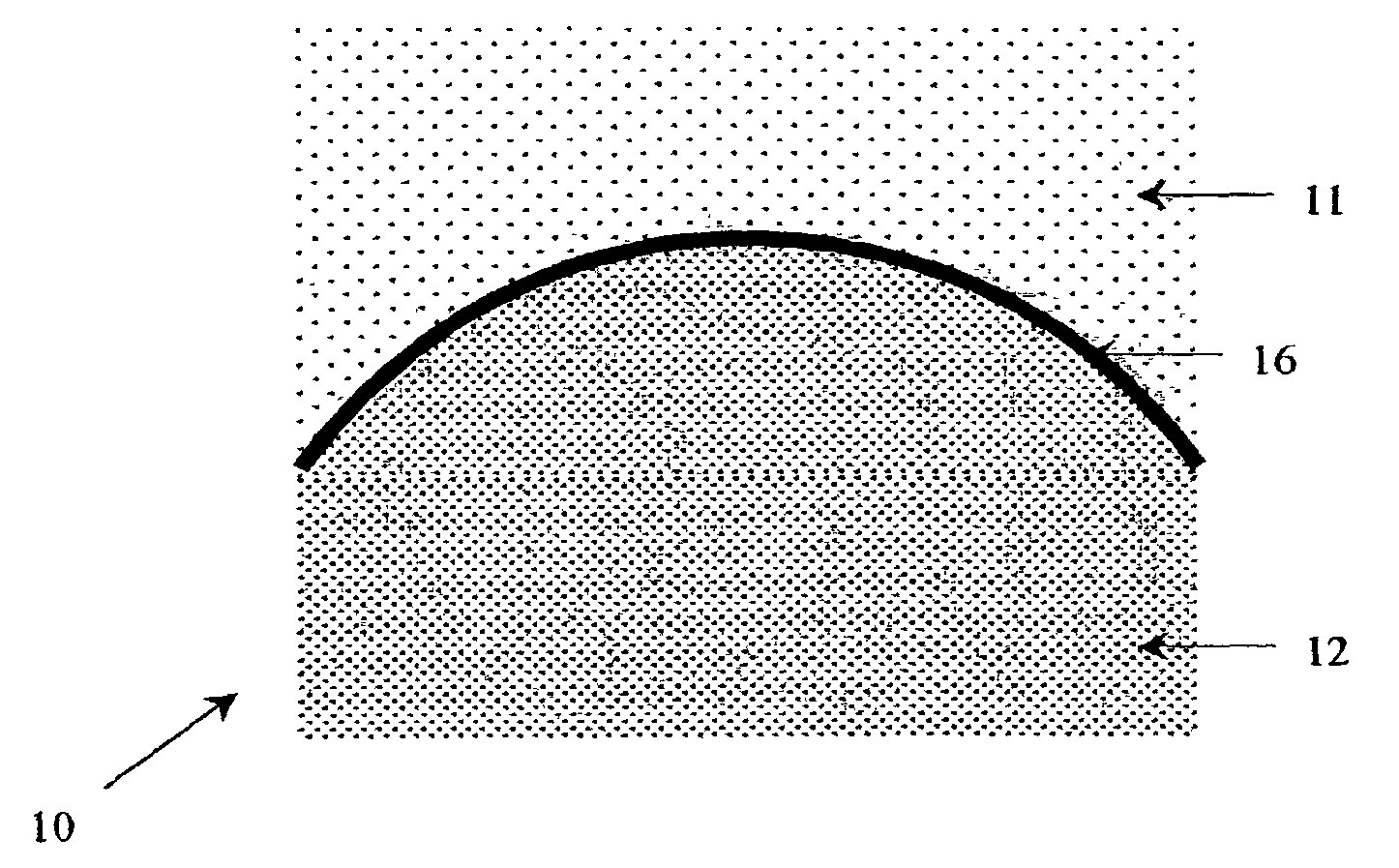
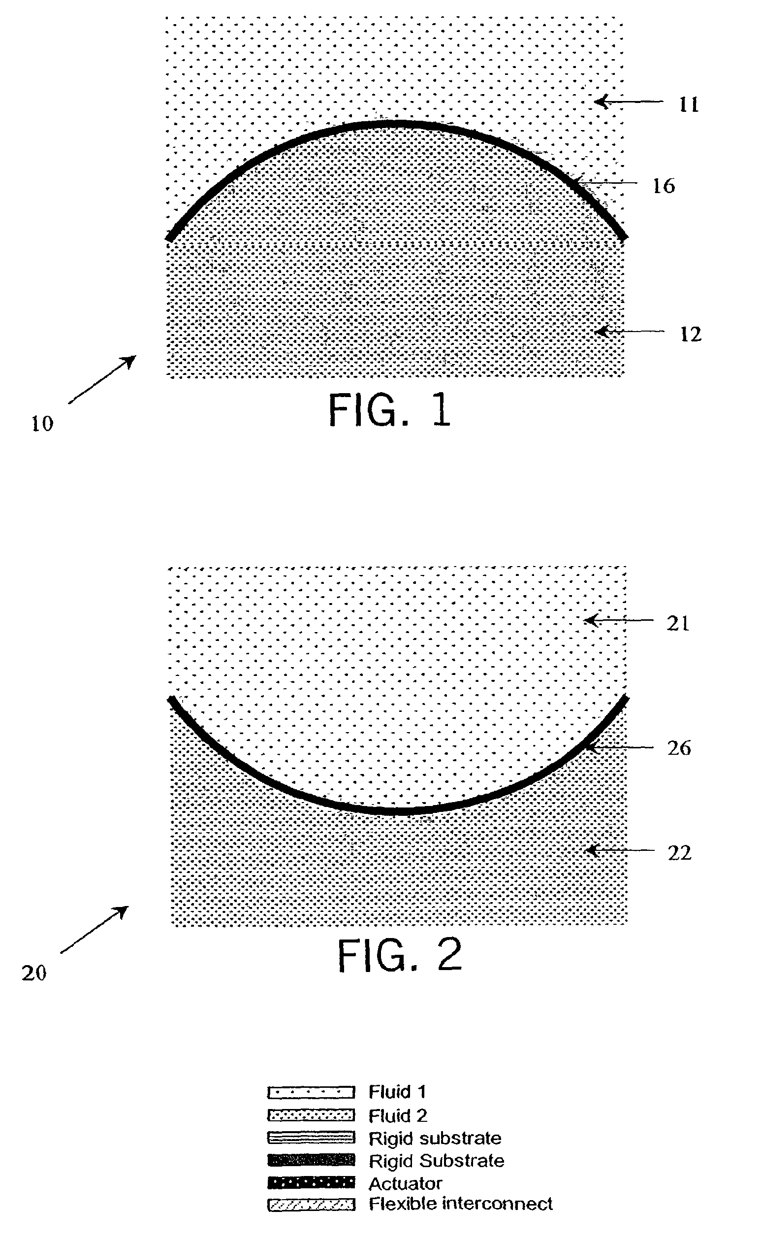
[0028]Referring to FIGS. 1-4, cross-sections of exemplary fluidic adaptive lenses are shown in schematic form. As particularly shown in FIG. 1, a first fluidic adaptive lens (or simply fluidic lens) 10 is a convex lens that includes a first medium 12 that is a higher index fluid, a second medium 11 that is a lower index fluid, and a flexible membrane or diaphragm 16 that separates the two media. The flexible membrane 16 is bent toward the side of the second medium 11 (the lower index side) as shown due to the pressure of the first medium 12 being greater than that of the second medium (plus some minimal pressure exerted by the membrane itself). In contrast to FIG. 1, FIG. 2 shows a second fluidic lens 20 that is a concave lens that includes a first medium 22 that is a higher index fluid, a second medium 21 that is a lower index fluid, and a flexible membrane (or diaphragm) 26 that separates the two media. The membrane 26 in contrast to the membrane 16 is bent toward the side of the ...


PUM


Abstract

The present invention in various embodiments relates to a variety of different types of fluidic adaptive lens systems, pumping systems for implementation in such lens systems, other systems employing such lens systems, and related methods of fabrication. In at least some embodiments, the present invention relates to a lens system that includes a reservoir having at least one flexible wall, a first actuator coupled in relation to the reservoir, and a terminal at which is located at least one of an integrated fluidic lens and a port configured to be coupled to an external fluidic lens. The terminal is coupled to at least one of the reservoir and the actuator, and at least one of the actuator and a first pumping system including the actuator is capable of causing fluid to be moved at least one of from the reservoir toward the terminal, and from the terminal toward the reservoir.

Description

CROSS-REFERENCE TO RELATED APPLICATIONS[0001]This application claims the benefit of U.S. provisional patent application No. 60 / 625,419 entitled “Tunable Fluidic Lenses With Integrated Micropumps” filed on Nov. 5, 2004, which is hereby incorporated by reference herein.STATEMENT REGARDING FEDERALLY SPONSORED RESEARCH OR DEVELOPMENT[0002]This invention was made with United States Government support awarded by the following agency: United States Air Force / Air Force Office of Scientific Research (USAF / AFOSR) Grant No. F49620-02-1-0426. The United States Government has certain rights in this invention.FIELD OF THE INVENTION[0003]The present invention relates to optical lenses such as can be employed in vision correction glasses, microscopes, zoom lens systems, cameras, and other applications.BACKGROUND OF THE INVENTION[0004]Optical lenses are employed in a variety of devices for many purposes such as modifying focus and magnification. Many conventional devices that employ optical lenses u...

Claims


Application Information

Patent Timeline
Patent Type & Authority Applications(United States)
IPC IPC(8): G02B3/12F04B17/00
CPCG02B26/005G02B3/14
Inventor JUSTIS, NICOLE B.ZHANG, DE-YINGLO, YU-HWA
Owner RGT UNIV OF CALIFORNIA
Why Eureka
Try Eureka