
Eureka
For R&D, Eureka makes reading and utilizing patents & technical documents easy.
Eureka AIR
Designed for self-driven R&D workflows. Generate viable solutions, solve complex R&D challenges, empower your innovation with AI.

Eureka Materials
Designed for material experts only. Revolutionize your material R&D, from search, analyze, to developing new materials.

TechResearch
Generate reliable direction feasibility study reports for your R&D in just a few steps.

TechSeek
Discover and master advanced knowledge NOW. Basics, ideas, possibilities, all at once.

TechMind
As an expert in R&D Theories, TechMind can generates customized viable solutions instantly.

TechRisk
Analyze your overall solution with one click, know your potential R&D risks in advance.

TechMonitor
Get weekly tech updates, stay abreast of the latest tech innovations and key insights.
Zoom lens, optical apparatus equipped with the zoom lens and method for forming an image of an object and varying a focal length
- Summary
- Abstract
- Description
- Claims
- Application Information
AI Technical Summary
Benefits of technology
Problems solved by technology
Method used
Image

Examples
embodiments
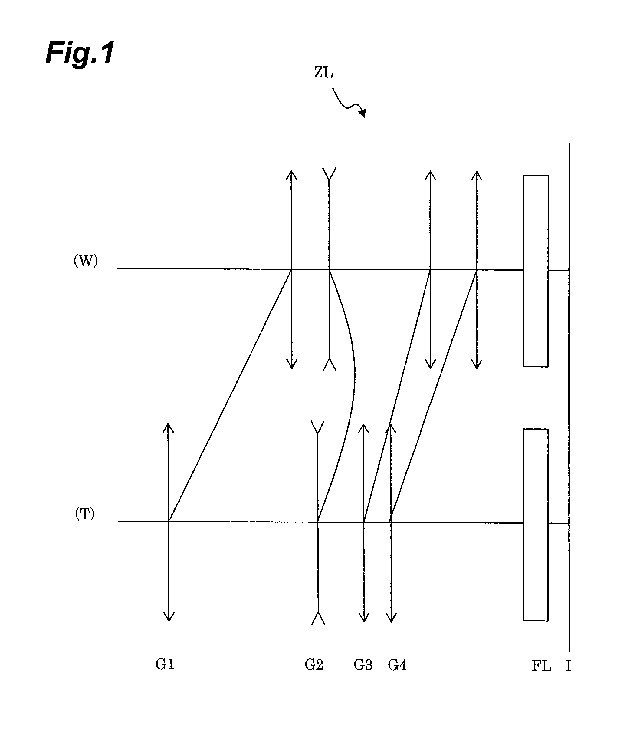
[0087]Each of embodiments of the present invention will be described below on the basis of the accompanying drawings. FIG. 1 is a drawing showing a refracting power layout of a zoom lens ZL according to the present embodiment and a state of movement of each of lens groups with a change in the focal length state from the wide-angle end state (W) to the telephoto end state (T). As shown in this FIG. 1, the zoom lens ZL of the present embodiment is composed of the following components in the order from the object side: a first lens group G1 having a positive refracting power; a second lens group G2 having a negative refracting power; a third lens group G3 having a positive refracting power; a fourth lens group G4 having a positive refracting power; and a filter group FL consisting of a low-pass filter, an infrared cut filter, and so on. With the change in the focal length state from the wide-angle end state to the telephoto end state (i.e., during carrying out zooming), the first lens ...
first embodiment
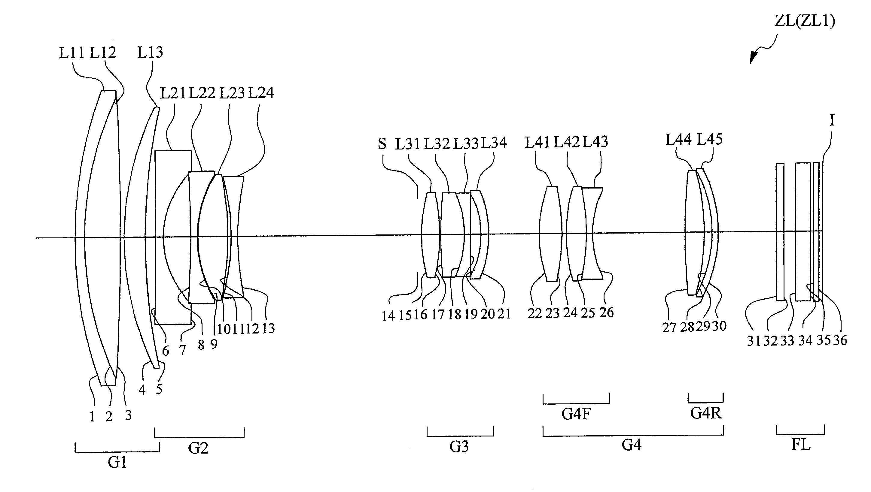
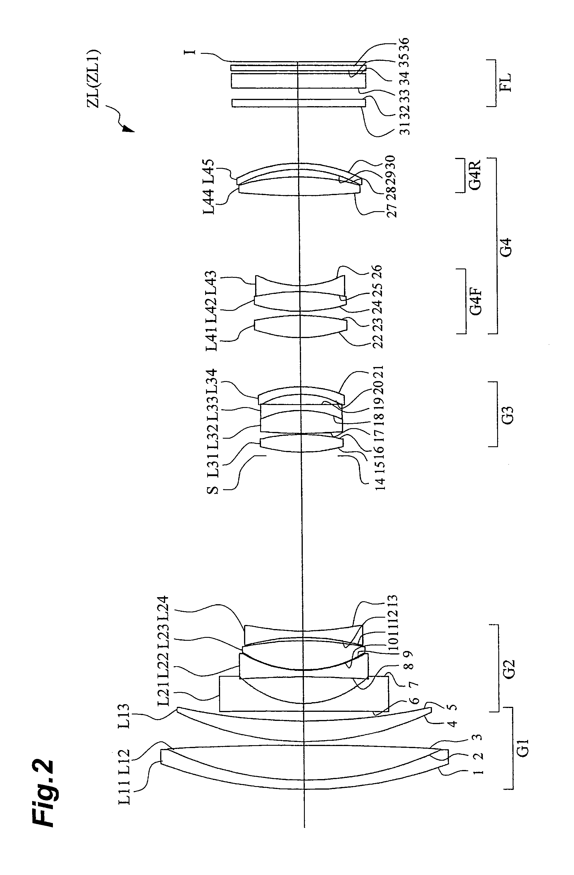
[0090]FIG. 2 is a drawing showing a configuration of a zoom lens ZL1 according to the first embodiment of the present invention. In this zoom lens ZL1 of FIG. 2, the first lens group G1 is composed of a cemented positive lens consisting of a negative meniscus lens L11 with a convex surface on the object side and a biconvex lens L12 cemented together, and a positive meniscus lens L13 with a convex surface on the object side, which are arranged in the order from the object side. The second lens group G2 is composed of a biconcave lens L21 with an aspherical surface on the image side, a biconcave lens L22, a biconvex lens L23, and a biconcave lens L24, which are arranged in the order from the object side. The third lens group G3 is composed of a biconvex lens L31, a cemented negative lens consisting of a biconvex lens L32 and a biconcave lens L33 cemented together, and a negative meniscus lens L34 with an aspherical surface on the image side and a concave surface on the object side, wh...
second embodiment
[0099]FIG. 5 is a drawing showing a configuration of a zoom lens ZL2 according to the second embodiment of the present invention. In this zoom lens ZL2 of FIG. 5, the first lens group G1 is composed of a cemented positive lens consisting of a negative meniscus lens L11 with a convex surface on the object side and a biconvex lens L12 cemented together, and a positive meniscus lens L13 with a convex surface on the object side, which are arranged in the order from the object side. The second lens group G2 is composed of a biconcave lens L21 with an aspherical surface on the image side, a biconcave lens L22, a biconvex lens L23, and a biconcave lens L24, which are arranged in the order from the object side. The third lens group G3 is composed of a biconvex lens L31, a cemented negative lens consisting of a biconvex lens L32 and a negative meniscus lens L33 with a convex surface on the image side cemented together, and a negative meniscus lens L34 with an aspherical surface on the image ...
PUM
 Abstract
Description
Claims
Application Information
 - R&D Engineer
- R&D Manager
- IP Professional
- Industry Leading Data Capabilities
- Powerful AI technology
- Patent DNA Extraction
Browse by: Latest US Patents, China's latest patents, Technical Efficacy Thesaurus, Application Domain, Technology Topic, Popular Technical Reports.
© 2024 PatSnap. All rights reserved.Legal|Privacy policy|Modern Slavery Act Transparency Statement|Sitemap|About US| Contact US: help@patsnap.com