
Method and System for Dynamic Image Processing

a dynamic image and processing technology, applied in image data processing, program control, instruments, etc., can solve the problems of limited computing resources on the image server that are available to conduct image processing functions for any particular client device, and the processing function at the image server does not take into account existing processing demands already placed on the image server

Active Publication Date: 2009-05-28
T2PHARMA GMBH
View PDF35 Cites 90 Cited by
  • Summary
  • Abstract
  • Description
  • Claims
  • Application Information

AI Technical Summary

Benefits of technology

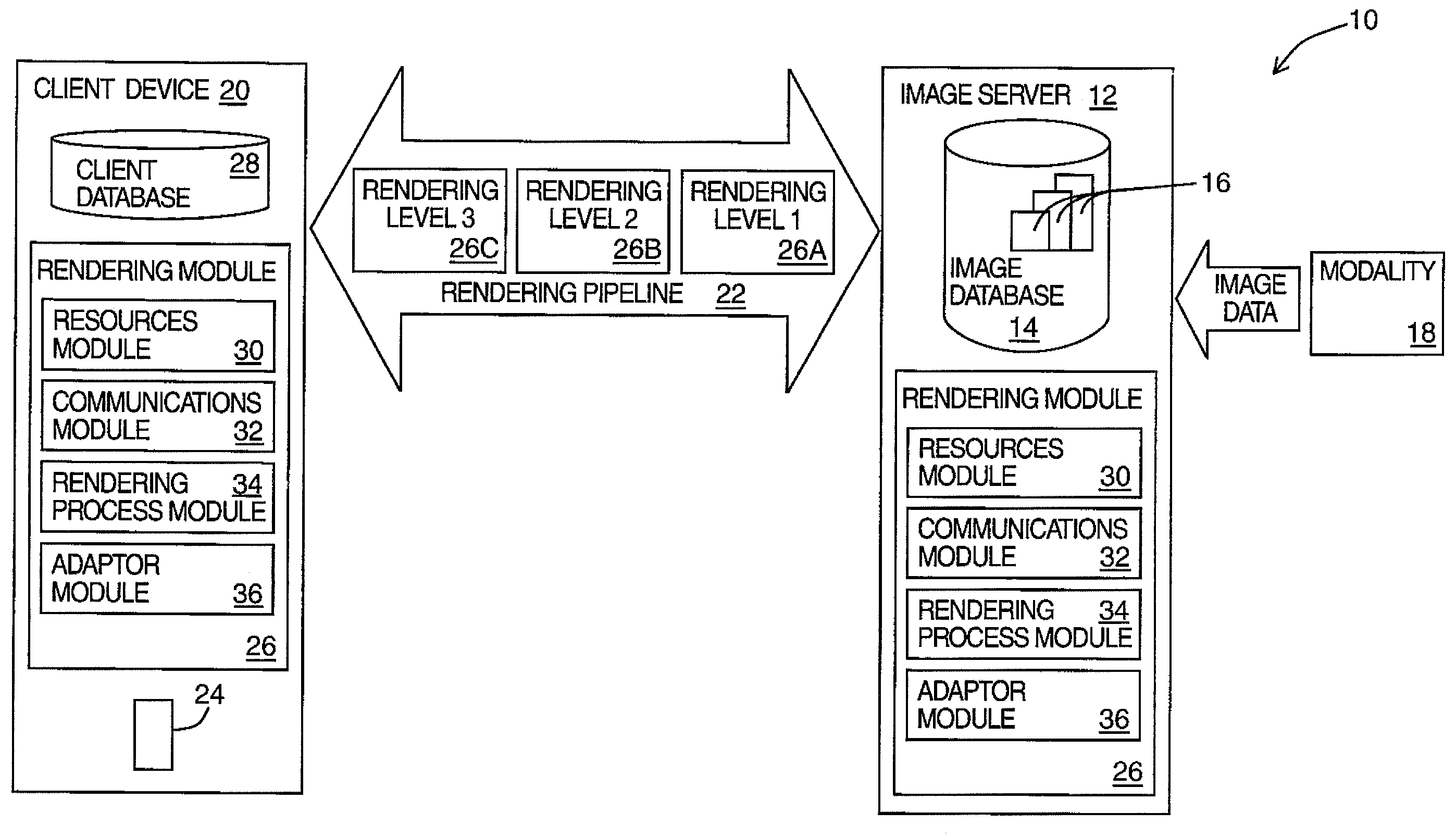
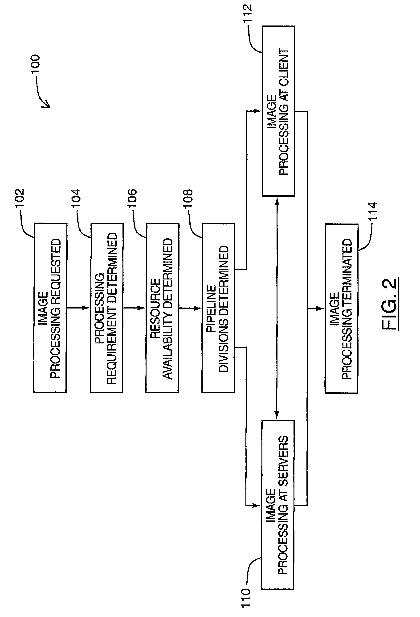
[0008]The embodiments described herein provide in one aspect a method of processing an image wherein one or more processing functions are executed, the method comprising: (a) determining the steps involved in the one or more processing functions wherein each of the one or more processing functions may comprise one or more processing steps; (b) determining one or more resource requirements associated with each of the one or more processing functions; (c) determining a resource availability for the one or more resource requirements upon a client; and (d) selectively allocating each of the one or more processing functions to at least one of the client and the server where the client does not have the required resource availability.

Problems solved by technology

The processing functions that are associated with the rendering and display of a requested medical image often entail intensive processing (i.e. computing overhead).
Therefore, the processing functions are often executed at the image server as the client devices are not suited to perform such processing.
However, processing such functions at the image server does not take into consideration existing processing demands already placed on the image server.
Accordingly, the computing resources on the image server that are available to conduct image processing functions for any particular client device are limited by overall traffic patterns and usage demands placed on the image server.

Method used


Image

  • Method and System for Dynamic Image Processing
  • Method and System for Dynamic Image Processing
  • Method and System for Dynamic Image Processing

Examples


Embodiment Construction

[0020]It will be appreciated that, for simplicity and clarity of illustration, where considered appropriate, reference numerals may be repeated among the figures to indicate corresponding or analogous elements or steps. In addition, numerous specific details are set forth in order to provide a thorough understanding of the exemplary embodiments described herein. However, it will be understood by those of ordinary skill in the art that the embodiments described herein may be practiced without these specific details. In other instances, well-known methods, procedures and components have not been described in detail so as not to obscure the embodiments described herein. Furthermore, this description is not to be considered as limiting the scope of the embodiments described herein in any way but rather as merely describing the implementation of the various embodiments described herein.

[0021]The embodiments of the systems and methods described herein may be implemented in hardware or sof...


PUM


Abstract

A method of processing an image wherein one or more processing functions are executed. Firstly, the steps involved in the one or more processing functions are determined where each of the one or more processing functions can include one or more processing steps. Secondly, the resource requirements associated with each of the processing functions are determined. The resource availability for the one or more resource requirements on a client is determined. Thirdly, and finally, each of the one or more processing functions are selectively allocated to the at least one of the client and the server in the case where the client does not have the required resource availability.

Description

CROSS REFERENCE TO RELATED APPLICATION(S)[0001]This application claims benefit of and priority to U.S. Provisional Application Ser. No. 60 / 867,055, filed Nov. 22, 2006. The entire disclosure of which is herein incorporated by reference.BACKGROUND[0002]1. Field of the Invention[0003]The embodiments described herein relate generally to image processing methods and systems and, more specifically, to an improved method and system for performing image processing functions in client-server environments.[0004]2. Description of the Related Art[0005]Image processing functions in medical imaging applications are generally carried out on image data by a client device that has accessed an image server to retrieve stored image data. These image processing functions, when completed, cause the related medical images to be displayed on the client device. A medical practitioner is then able to analyze the medical images displayed on the client device.[0006]Increasingly, health professionals are usin...

Claims


Application Information

Patent Timeline
Patent Type & Authority Applications(United States)
IPC IPC(8): G06F15/16G06F15/173
CPCG06F9/5083G06T2200/16G06T1/20
Inventor WEGENKITTL, RAINERDENNISON, DONALD K.POTWARKA, JOHN J.MROZ, LUKASKANITSAR, ARMINZEILINGER, GUNTER
Owner T2PHARMA GMBH
Learn More