This helps you quickly interpret patents by identifying the three key elements:
Problems solved by technology
Method used
Benefits of technology
Problems solved by technology
The use of tape at the insertion site can retain dirt or other contaminant particles, potentially leading to infection of the patient.
Tape also fails to limit catheter motion and, therefore, contributes to motion related complications like phlebitis, infiltration and catheter migration.
Additionally, removal of taped dressings can itself cause undesired motion of the catheter upon the patient.
Such repeated applications of tape over the catheter or medical line can additionally lead to the build up of adhesive residue on the outer surface of the catheter or medical line.
This residue can result in contaminants adhering to the catheter itself, increasing the likelihood of infection of the insertion site.
This residue can also make the catheter or medical line stickier and more difficult to handle for healthcare providers.
Method used
Image
Click on the blue label to locate the original text in one second.
Reading with bidirectional positioning of images and text.
Examples
second embodiment
[0018]FIG. 6 is a perspective view of a retainer having a movable spine and ratchet arrangement to accommodate medical devices with different longitudinal lengths.
third embodiment
[0019]FIG. 7 is a perspective view of a retainer having two abutment surfaces located between the proximal and distal ends of the retainer body.
[0020]FIG. 8 is a top plan view of the retainer of FIG. 7.
[0021]FIG. 9 is a front side view of the retainer of FIG. 7.
[0022]FIG. 10 is a back side view of the retainer of FIG. 7.
[0023]FIG. 11 is a side view of the retainer of FIG. 7.
[0024]FIG. 12 is a cross section view taken along line 12-12 in FIG. 8 illustrating the abutment surfaces of the retainer.
[0025]FIG. 13 is a simplified perspective view of a medical article that includes contact surfaces corresponding to the abutment surfaces illustrated in FIG. 12.
[0026]FIG. 14 is a perspective view of the medical article illustrated in FIG. 13 secured to the retainer of FIG. 7.
[0027]FIG. 15 is a cross section view taken along line 15-15 in FIG. 14 illustrating the abutment surfaces of the retainer in register with the contact surfaces of the medical article.
fourth embodiment
[0028]FIG. 16 is a perspective view of a retainer having an abutment surface located between the proximal and distal ends of the retainer body.
[0029]FIG. 17 is a top plan view of the retainer of FIG. 16.
[0030]FIG. 18 is a front side view of the retainer of FIG. 16.
[0031]FIG. 19 is a back side view of the retainer of FIG. 16.
[0032]FIG. 20 is a side view of the retainer of FIG. 16.
[0033]FIG. 21 is a cross section view taken along line 21-21 in FIG. 17 illustrating the abutment surface of the retainer.
[0034]FIG. 22 is a simplified perspective view of a medical article that includes a contact surface corresponding to the abutment surface illustrated in FIG. 21.
[0035]FIG. 23 is a perspective view of the medical article illustrated in FIG. 22 secured to the retainer of FIG. 16.
[0036]FIG. 24 is a cross section view taken along line 24-24 in FIG. 23 illustrating the abutment surface of the retainer in register with the contact surface of the medical article.
PUM
Abstract
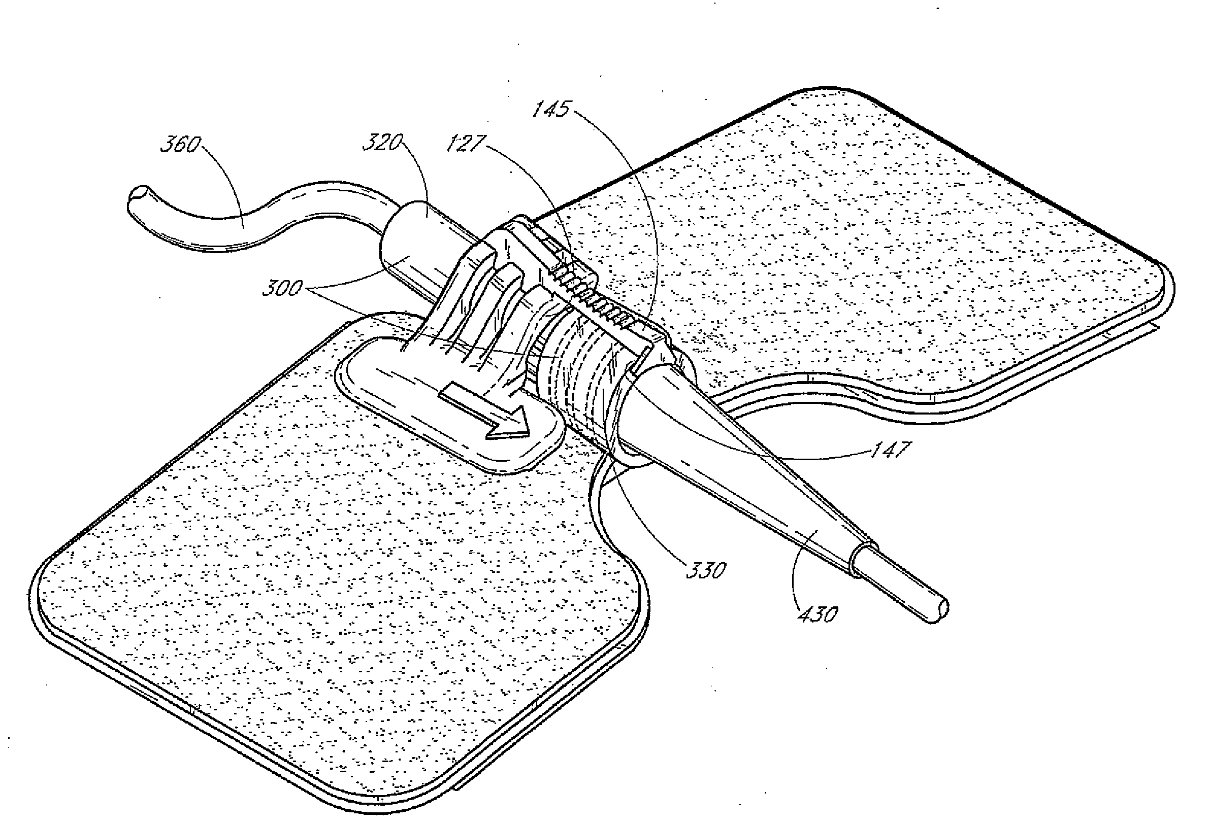
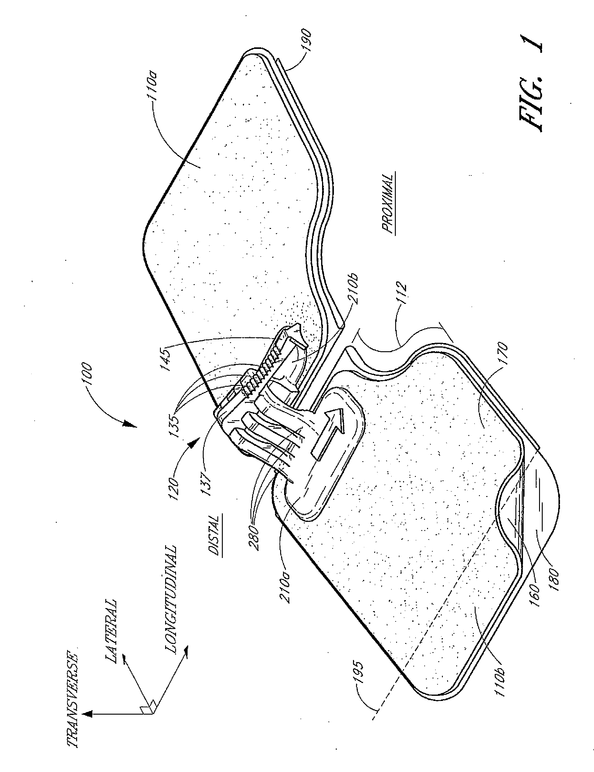
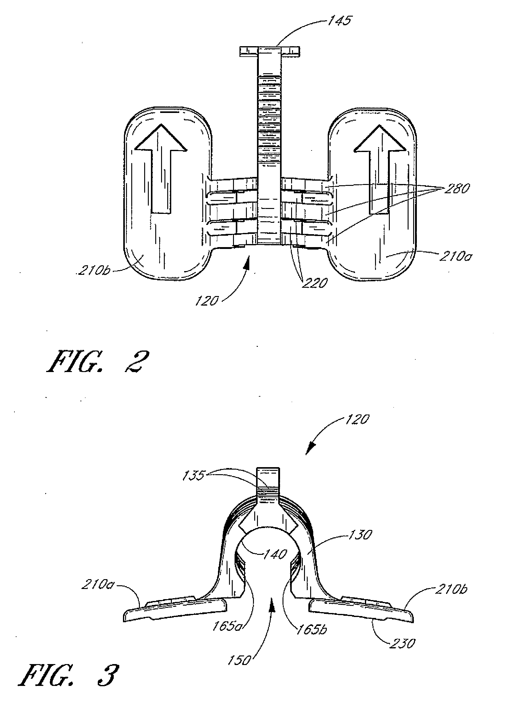
A catheter securement device (100) holds a medical article such as a catheter hub or a connector fitting in position upon the body of a patient and at least inhibits longitudinal movement of the medical article. The securement device (100) includes a retainer (120) and at least one anchor pad (110). The retainer (120) has one or more curved ribs (280) into which at least a portion of the medical article is inserted. The retainer (120) includes a spine (145) that extends in a proximal direction from the retainer (120). The spine (145) includes a clip (147) having an abutment surface that can abut against a contact point or surface on the medical article. The abutment, in conjunction with a second abutment and / or a tapering shape of the retainer (120), inhibits longitudinal movement of the medical article in both proximal and distal directions.
Description
RELATED APPLICATIONS[0001]This application claims the benefit of U.S. Provisional Application No. 60 / 710,322, filed Aug. 22, 2005, which is hereby incorporated by reference in its entirety.BACKGROUND[0002]1. Field of the Invention[0003]This invention relates to a securement system used to attach a medical line to a patient.[0004]2. Description of the Related Art[0005]It is common in the treatment of patients to utilize catheters to introduce fluids and medications directly into the patient or to withdraw fluids from the patient. Often, it becomes desirable to maintain such catheterization over an extended period of time during the treatment of a patient. In order to keep the catheter or other medical line properly positioned for the duration of treatment, the catheter or medical line can be secured to the patient in a variety of ways. Most commonly, this involves taping the catheter or medical line to the patient.[0006]Securing a catheter with tape upon the patient traditionally has...
Claims
Application Information
Patent Timeline
Application Date:The date an application was filed.
Publication Date:The date a patent or application was officially published.
First Publication Date:The earliest publication date of a patent with the same application number.
Issue Date:Publication date of the patent grant document.
PCT Entry Date:The Entry date of PCT National Phase.
Estimated Expiry Date:The statutory expiry date of a patent right according to the Patent Law, and it is the longest term of protection that the patent right can achieve without the termination of the patent right due to other reasons(Term extension factor has been taken into account ).
Invalid Date:Actual expiry date is based on effective date or publication date of legal transaction data of invalid patent.

