Door hinge

a door hinge and hinge pin technology, applied in the field of hinges, can solve the problems of uneven wear of hinge components, concentrated load on hinge pins, and undesirable looseness of hinge components

Active Publication Date: 2009-06-18
LIBERTY HARDWARE MFG
View PDF34 Cites 24 Cited by
  • Summary
  • Abstract
  • Description
  • Claims
  • Application Information

AI Technical Summary

Benefits of technology

[0006]An example bearing arrangement for hinge components includes a bearing mountable about a hinge pin that extends along a rotational axis. A tolerance ring is mountable about the bearing that biases the bearing to limit relative rotational movement between the hinge pin and a hinge knuckle about the rotational axis. The bearing arrangement may include a flange extending from the bearing to prevent a hinge knuckle on a first hinge half from contacting a hinge knuckle on the second hinge half.

Problems solved by technology

The knuckles rotate relative to each other and contact the hinge pin as the door moves, which may result in a concentrated load on the hinge pin.
Concentrated loads on the hinge pin can unevenly wear the hinge components.
Excessive clearance between the hinge components can result in undesirable looseness, sometimes referred to as chuck, as the door moves between open and closed positions.
Wearing the hinge surfaces increases clearance between hinge components, which increases looseness and chuck within the hinge assembly.
Particulate matter such as dust and dirt often undesirably accumulates within areas of clearance between the hinge components.

Method used


Image

  • Door hinge
  • Door hinge
  • Door hinge

Examples


Embodiment Construction

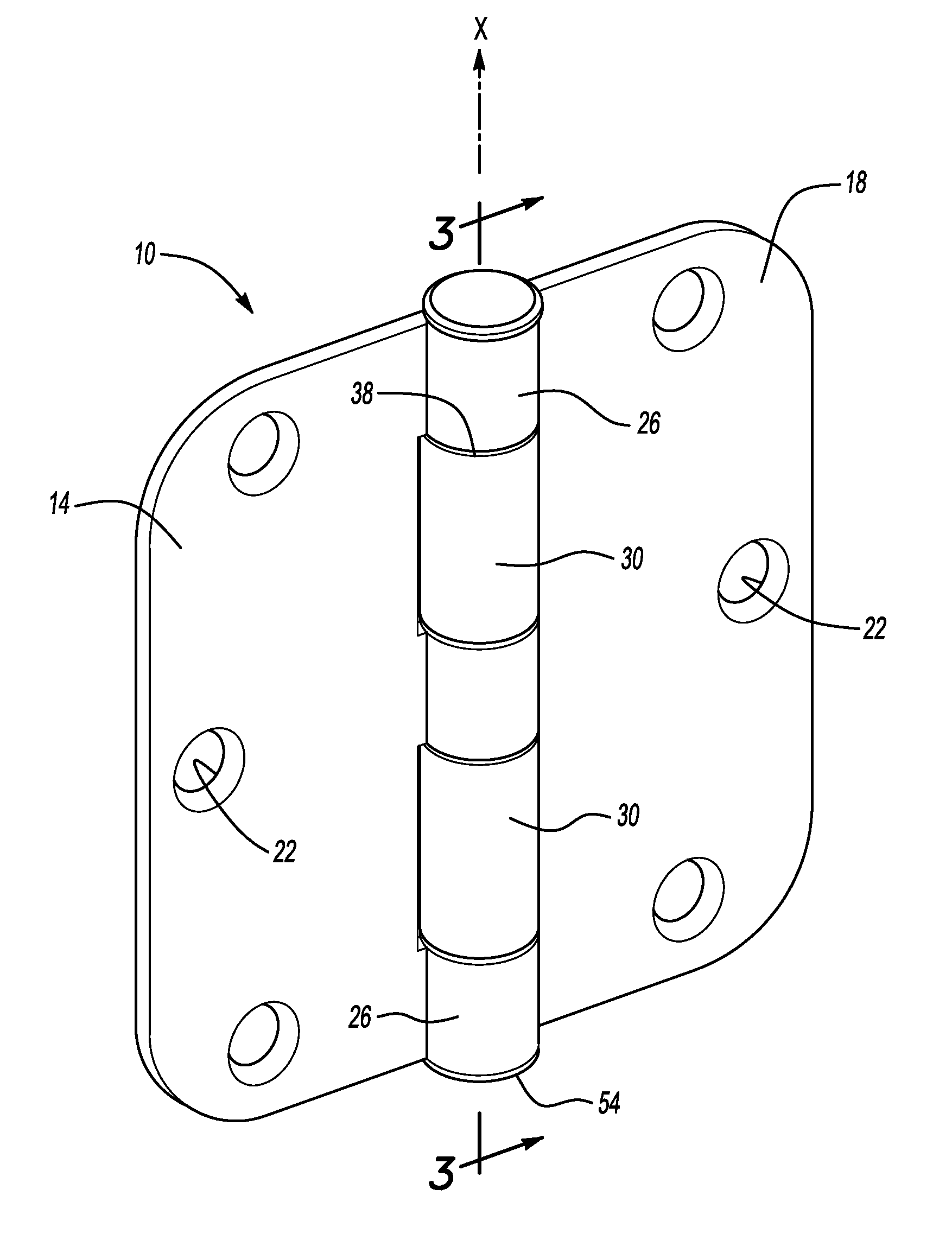
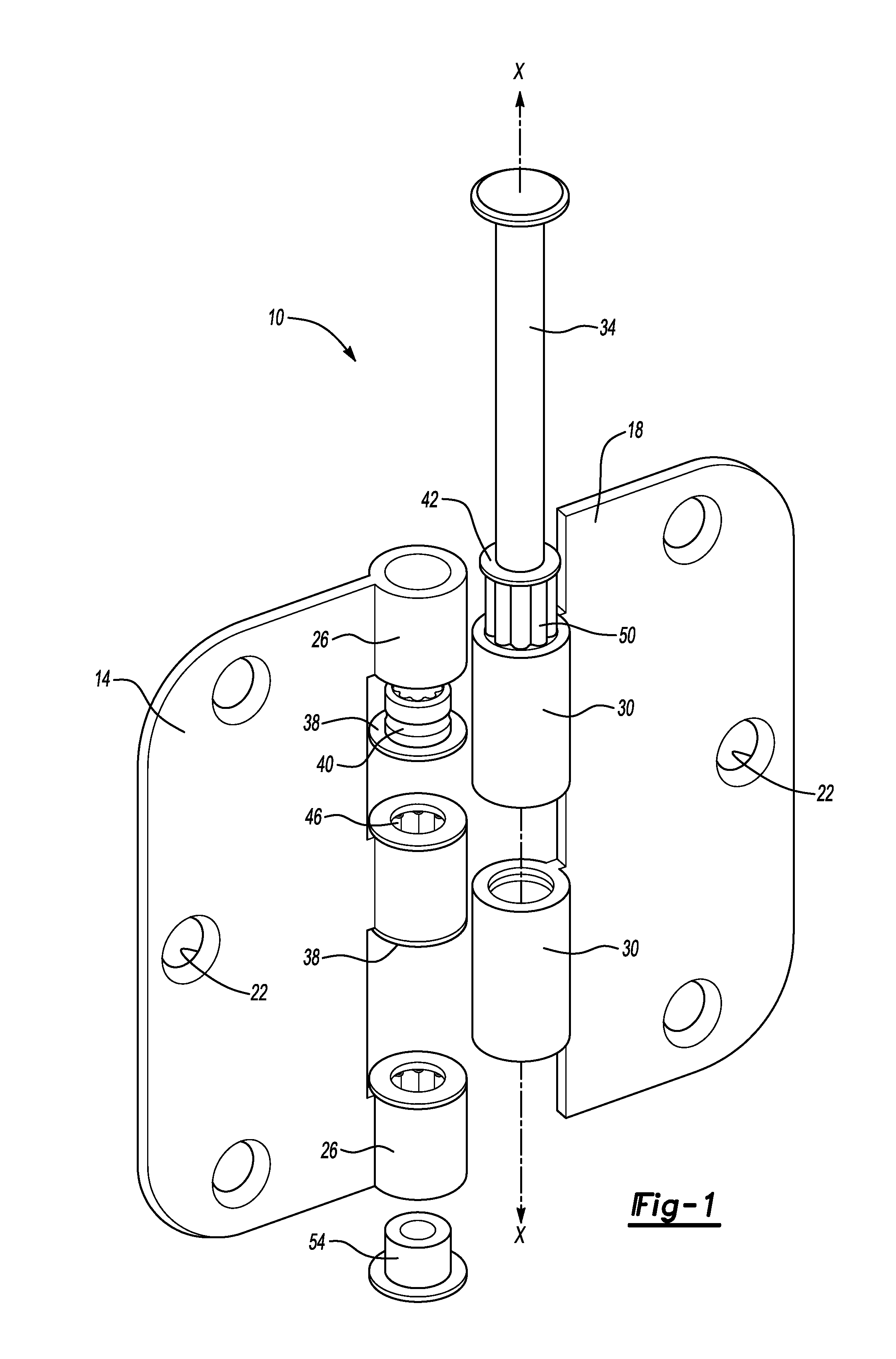
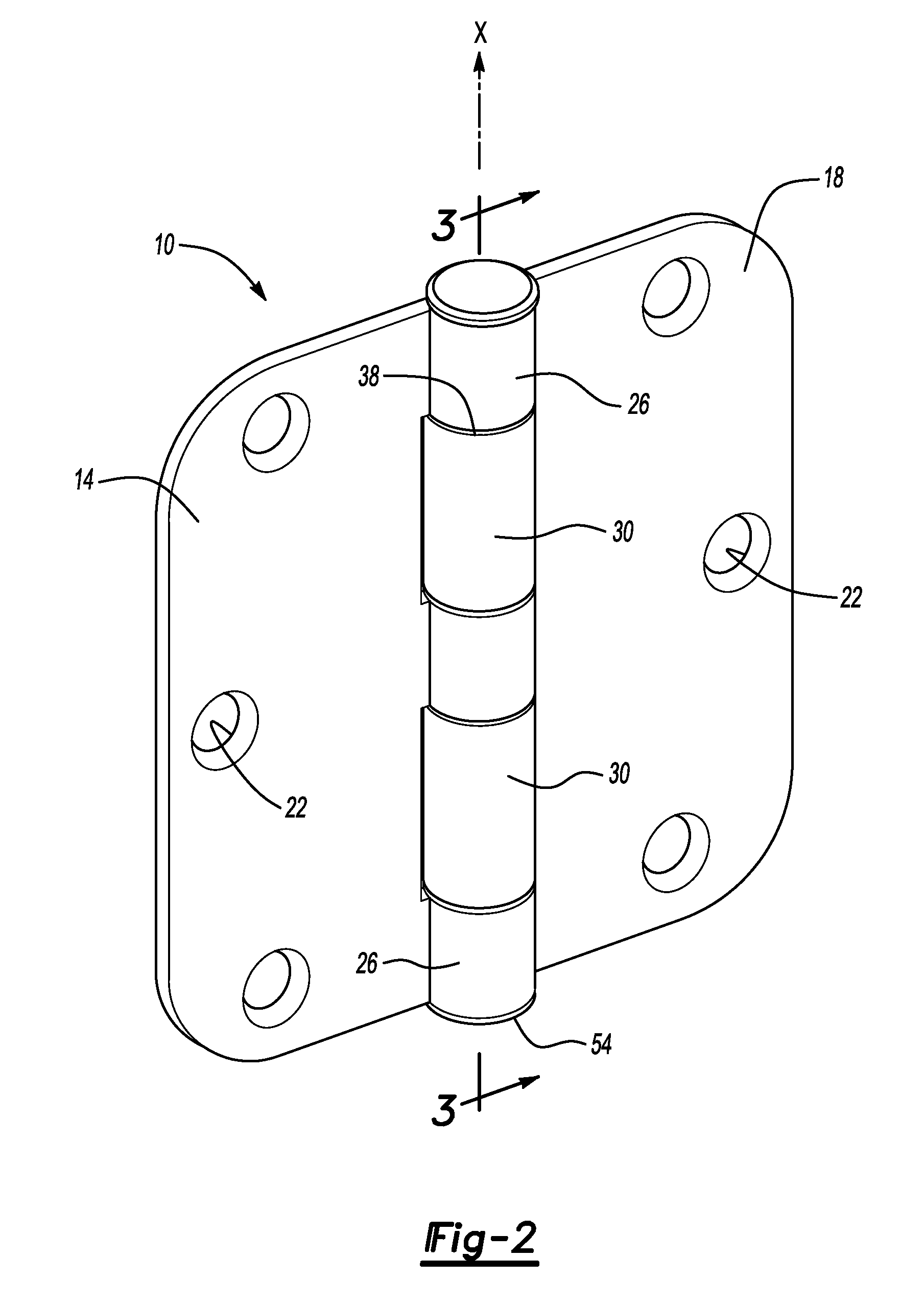
[0018]Referring to FIGS. 1 and 2, an example hinge assembly 10 includes a first hinge plate 14 and a second hinge plate 18. The first hinge plate 14 and the second hinge plate 18 include a plurality of apertures 22 for securing the hinge assembly 10 to a door and a door frame in a known manner.

[0019]A first knuckle 26 extends from the first hinge plate 14. A second knuckle 30 extends from the second hinge plate 18. The first knuckle 26 and the second knuckle 30 receive a hinge pin 34, which joins the first hinge plate 14 to the second hinge plate 18. The hinge pin 34 extends along an axis X. When assembled, the first hinge plate 14 moves relative the second hinge plate 18 by rotating about the axis X.

[0020]The first knuckle 26 also receives a thrust bearing 38 for limiting radial and axial movement of the hinge pin 34. The second knuckle 30 receives a radial bearing 42. The thrust bearing 38 includes a tolerance ring 46, a type of biasing member, adjacent an inner surface. The radia...


PUM

PropertyMeasurementUnit
relative movementaaaaaaaaaa
movementaaaaaaaaaa
relative rotational movementaaaaaaaaaa

Abstract

An example hinge includes a hinge pin extending along an axis and a first knuckle for receiving the hinge pin. The first knuckle is rotatable about the axis. A second knuckle for receiving the hinge pin and is rotatable about the axis. At least one bearing limits relative rotation between the first hinge knuckle and the hinge pin. The example hinge assembly may include a tolerance ring between the hinge pin and the first knuckle to urge the bearing away from the axis. An example method of producing a hinge includes the steps of permitting a first hinge plate to move relative a hinge pin and limiting movement of a second hinge plate relative a hinge pin. The method biases a bearing adjacent the hinge pin to limit movement of the second hinge plate relative the hinge pin.

Description

BACKGROUND OF THE INVENTION[0001]This invention relates generally to a hinge and a method of fabricating a hinge with reduced clearance between hinge components.[0002]Residential hinges secure a door to a door frame. Some known hinges maintain or hold the door position as the door opens and closes. Smooth door movements are desirable, especially in residential environments.[0003]Typical hinges include a hinge pin extending through knuckles to pivotably join two hinge halves. The knuckles rotate relative to each other and contact the hinge pin as the door moves, which may result in a concentrated load on the hinge pin. Concentrated loads on the hinge pin can unevenly wear the hinge components. In some hinges, metal hinge pins can rub against metal hinge knuckles as the hinge moves.[0004]Excessive clearance between the hinge components can result in undesirable looseness, sometimes referred to as chuck, as the door moves between open and closed positions. Wearing the hinge surfaces in...

Claims


Application Information

Patent Timeline
Patent Type & Authority Applications(United States)
IPC IPC(8): E05D11/06E05D11/00B21D53/40
CPCE05D5/128E05D5/14E05D11/06E05Y2900/132Y10T16/557Y10T16/537Y10T29/24Y10T16/551Y10T16/5518Y10S16/27E05Y2201/632
Inventor FORREST, EARL DAVID
Owner LIBERTY HARDWARE MFG
Why Eureka
Try Eureka