MEMS resonator array structure and method of operating and using same

a resonator array and micro-electromechanical technology, applied in the direction of oscillator generators, impedence networks, electrical apparatus, etc., can solve the problems of reducing driving and/or sensing capacitance, adversely affecting signal strength, stability and/or the “q” factor of the resonator

Active Publication Date: 2009-06-18
ROBERT BOSCH GMBH
View PDF13 Cites 34 Cited by
  • Summary
  • Abstract
  • Description
  • Claims
  • Application Information

AI Technical Summary

Benefits of technology

[0045]It should be understood that all aspects and/or embodiments of the present invention that are not described in this Summary of the Inv

Problems solved by technology

The smaller dimensions have led to reduced driving and/or sensing capacitances, which can

Method used


Image

  • MEMS resonator array structure and method of operating and using same
  • MEMS resonator array structure and method of operating and using same
  • MEMS resonator array structure and method of operating and using same

Examples


Embodiment Construction

[0158]There are many inventions described and illustrated herein, as well as many aspects and embodiments of those inventions.

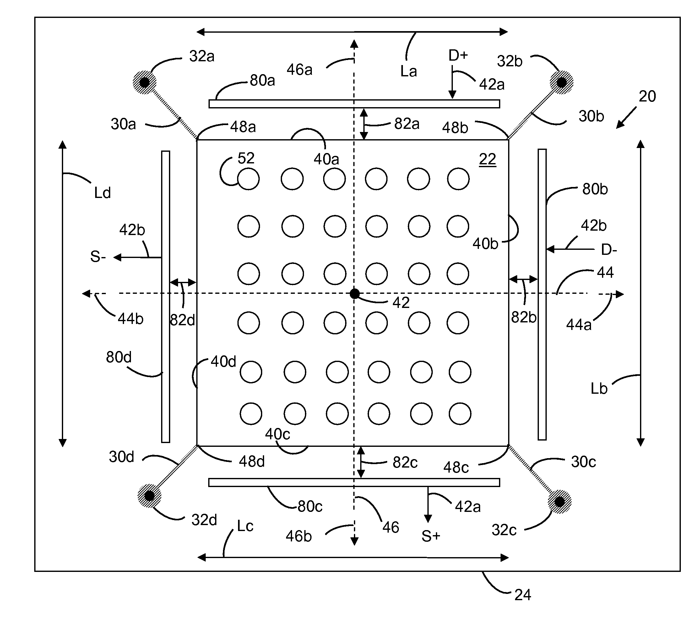
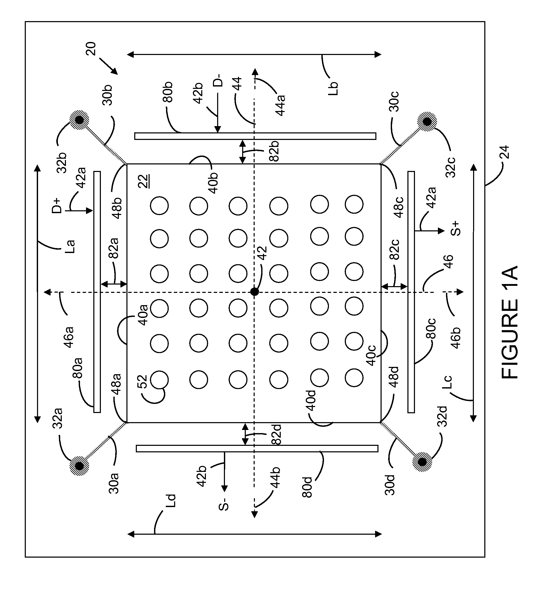
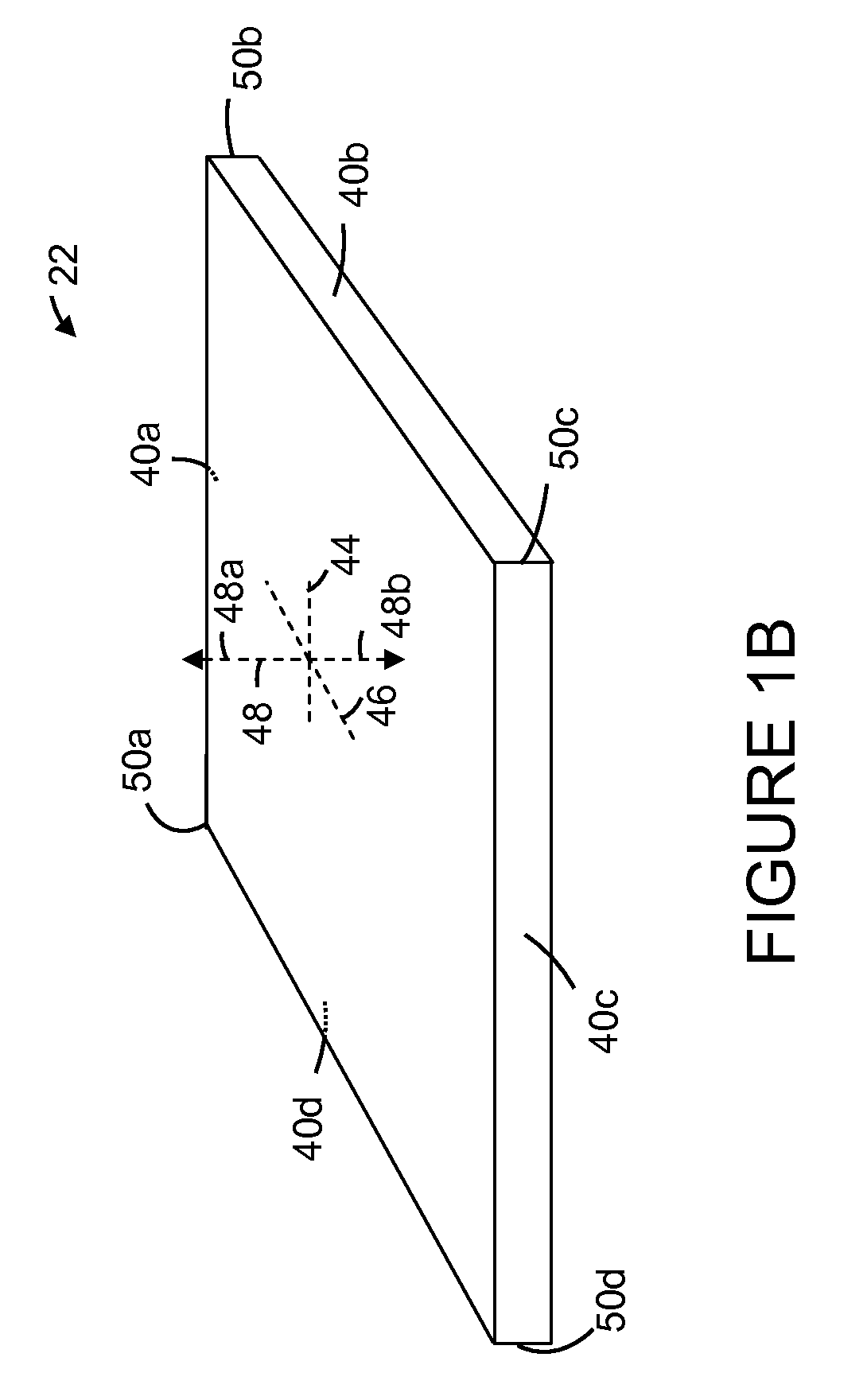
[0159]In one aspect, the present invention is directed to a microelectromechanical system that includes a plurality of bulk mode resonators arranged in an array. Each of the bulk mode resonators is mechanically coupled to one or more (i.e., one, some or all) other bulk mode resonators in the array. In one embodiment, each resonator of the array is mechanically coupled to at least one other bulk mode resonator by a resonator coupling section. For example, a resonator coupling section may be disposed between two or more resonators of the array to mechanically couple the two or more resonators. In one embodiment, each bulk mode resonator of the array is mechanically coupled to one or more other bulk mode resonators that are adjacent to the bulk mode resonator. In one embodiment, each bulk mode resonator of the array is mechanically coupled to all of the bulk mod...


PUM


Abstract

Each one of resonators arranged in an N×M MEMS array structure includes substantially straight elongated beam sections connected by curved/rounded sections and is mechanically coupled to at least one adjacent resonator of the array via a coupling section, each elongated beam section connected to another elongated beam section at a distal end via the curved/rounded sections forming a geometric shape (e.g., a rounded square), and the coupling sections disposed between elongated beam sections of adjacent resonators. The resonators, when induced, oscillate at substantially the same frequency, in combined elongating/breathing and bending modes, i.e., beam sections exhibiting elongating/breathing-like and bending-like motions. One or more of the array structure's resonators may include one or more nodal points (i.e., that are substantially stationary and/or experience little movement), which are suitable and/or preferable locations to anchor the resonator/array to the substrate, in one or more areas of the structure's curved sections.

Description

BACKGROUND[0001]This invention relates to microelectromechanical or nanoelectromechanical resonator structures and methods for use in association with resonator structures.[0002]Generally, high quality (“Q”) factor microelectromechanical resonators are regarded as a promising choice for frequency references and filters. However, to achieve higher frequencies, the dimensions of such resonators are being scaled smaller. The smaller dimensions have led to reduced driving and / or sensing capacitances, which can in turn adversely impact signal strength, stability and / or the “Q” factor of the resonator.[0003]There is a need for a resonator structure that helps overcome one, some or all of the shortcomings described above.SUMMARY OF THE INVENTION[0004]There are many inventions described and illustrated herein, as well as many aspects and embodiments of those inventions. This Summary discusses some of the inventions described and claimed herein. By no means is this Summary of the Invention i...

Claims


Application Information

Patent Timeline
IPC IPC(8): H03B5/30
CPCH03B5/30H03H9/02259H03H9/02338H03H9/2405H03H2009/02503H03H9/505H03H2009/0233H03H2009/02385H03H2009/0244H03H9/2447
Inventor LUTZ, MARKUSPAN, ZHIYUPARTRIDGE, AARON
Owner ROBERT BOSCH GMBH
Why Eureka
Try Eureka