Backlight Apparatus and Liquid Display Apparatus

a liquid display and backlight technology, applied in the field of backlight apparatus, can solve the problems of hard and the crt is difficult to increase the effect of eliminating the blur in the motion picture as equally. achieve the effect of increasing the effect of eliminating the blur in the motion pictur

Inactive Publication Date: 2009-06-18
PIONEER CORP
View PDF3 Cites 10 Cited by
  • Summary
  • Abstract
  • Description
  • Claims
  • Application Information

AI Technical Summary

Benefits of technology

[0011]That is, the CRT display apparatus displaces the point of light formed by the electron beam. Thus, it is one moment that the light is emitted in the same place in the display screen. In other words, it is long that the light is out in the same place in the display screen. As a result, according to the CRT display apparatus, it is possible to achieve the sufficient effect of eliminating the blur in the motion picture.
[0018]It is a second object of the present invention to provide a backlight apparatus and a liquid crystal display apparatus which can increase the effect of eliminating the blur in the motion picture while preventing the generation of the flicker.Means for Solving the Subject

Problems solved by technology

In the aforementioned technologies, however, there is such a technical problem that it is hard to increase an effect of eliminating the blur in the motion picture as equally as the CRT display does.
As a result, in the technology disclosed in the aforementioned Japanese Patent Application Laid Open No. 2000-321993 or Japanese Patent Application Laid Open No. 2001-92370, it is hard to increase the effect of eliminating the blur in the motion picture as equally as the CRT display does.

Method used


Image

  • Backlight Apparatus and Liquid Display Apparatus
  • Backlight Apparatus and Liquid Display Apparatus
  • Backlight Apparatus and Liquid Display Apparatus

Examples


first embodiment

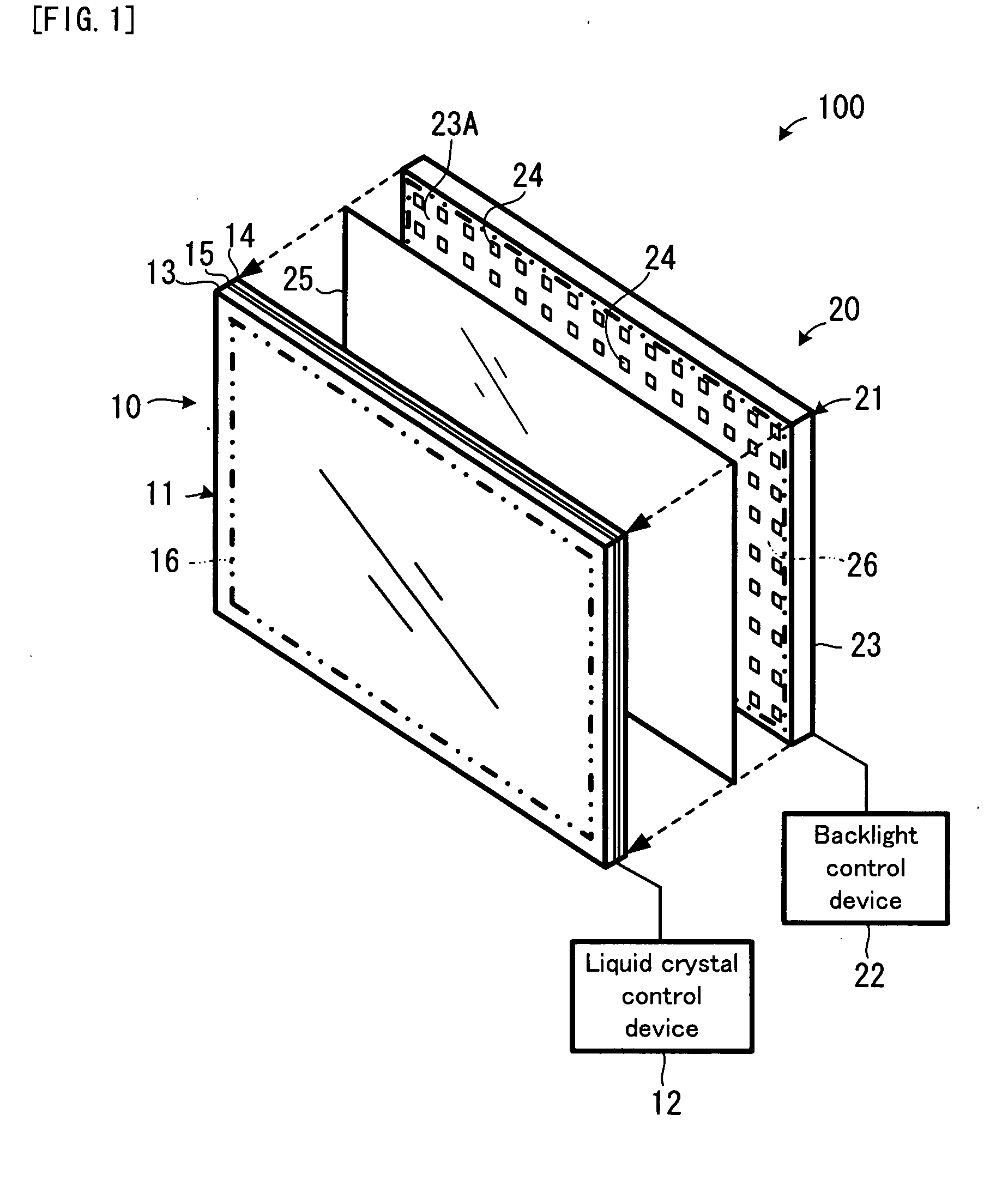
[0064]FIG. 1 shows a first embodiment of the liquid crystal display apparatus of the present invention. A liquid crystal display apparatus 100 in FIG. 1 is an apparatus for displaying an image on a display screen. The liquid crystal display apparatus 100 is provided with: a liquid crystal display panel unit 10; and a backlight unit 20.

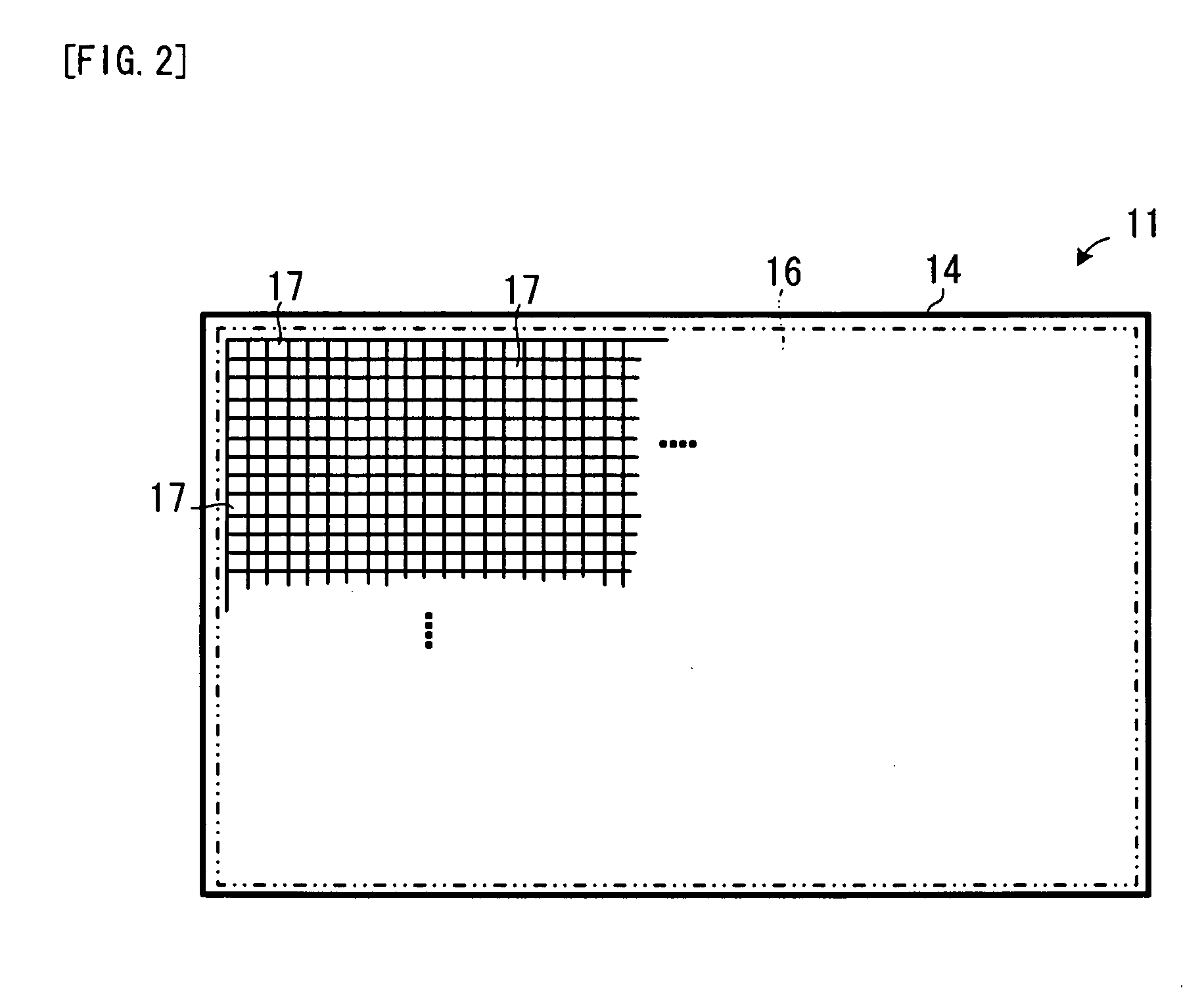
[0065]The liquid crystal display panel unit 10 is a unit for displaying an image on a display screen 16 by changing the light transmittance of a liquid crystal 15 disposed between two display substrates 13 and 14. The liquid crystal display panel unit 10 is provided with: a display panel main body 11; and a liquid crystal control device 12.

[0066]In the display panel main body 11, each of the display substrates 13 and 14 is, for example, a glass substrate. Each of the display substrates 13 and 14 is provided with: an oriented film on the inner surface facing the liquid crystal 15; and a polarizing plate on the outer surface. Moreover, each of the displa...

second embodiment

[0109]FIG. 12 shows a backlight control device of a backlight unit in a second embodiment of the liquid crystal display apparatus of the present invention. On the backlight unit in the second embodiment, an area with a motion in the image displayed on the display screen, i.e. a motion area, is detected, and luminous point is displaced only in a partial area in the backlight area corresponding to the motion area, or only in a partial area in the backlight area corresponding to a partial area in the display screen including the motion area. Incidentally, the structure of the second embodiment of the liquid crystal display apparatus is the same as that of the first embodiment of the liquid crystal display apparatus, except for a backlight control device 30 shown in FIG. 12.

[0110]As shown in FIG. 12, the backlight control device 30 of the backlight unit in the second embodiment is provided with: a light emission control device 31; a motion area detecting device 32; and a light amount ad...

example

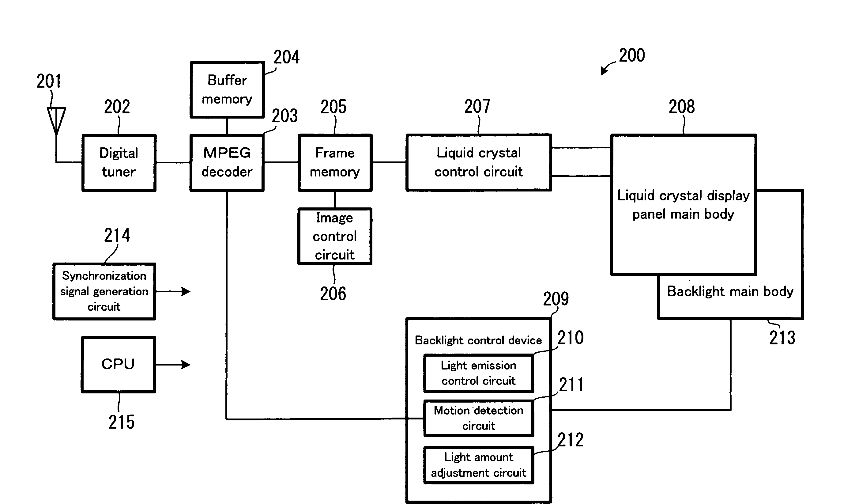
[0126]Hereinafter, the example of the present invention will be explained with reference to FIG. 16. In the following example, the backlight apparatus or the liquid crystal display apparatus of the present invention is applied to a liquid crystal television system.

[0127]In a liquid crystal television system 200 in FIG. 16, a digital television signal transmitted from a television broadcast station is received by an antenna 201 and inputted to a digital tuner 202. The digital tuner 202 extracts image data about one program from among the digital television signal, and supplies this to a MPEG decoder 203. The MPEG decoder 203 cooperates with a buffer memory 204, to thereby decode the image data, and supplies the decoded image data to a frame memory 205. An image control circuit 206 generates interpolated image data or the like if necessary. The frame memory 205 holds the image data decoded by the MPEG decoder 203 or the interpolated image data generated by the image control circuit 20...


PUM

PropertyMeasurementUnit
optical transmittanceaaaaaaaaaa
areaaaaaaaaaaa
displacementaaaaaaaaaa

Abstract

By controlling light emission, non-emission, and light intensity of each of the light emitting elements arranged on a backlight unit, a point-shaped light emitting point is created and the light emitting point is moved along the arrangement of pixels formed on a liquid crystal display panel unit. By moving the light emitting point as if an electron beam were scanning in the CRT display, it is possible to enhance the dynamic image blur removal effect.

Description

TECHNICAL FIELD[0001]The present invention relates to a backlight apparatus suitable to be used for a liquid crystal display apparatus or the like, and a liquid crystal display apparatus.BACKGROUND ART[0002]Lately, the spread of a so-called flat display apparatus, such as a liquid crystal display apparatus, a plasma display apparatus, and an organic EL (Electroluminescence) display apparatus, has been growing. In the market of a television, a monitor for a personal computer, or the like, the flat display apparatus is getting more general than a CRT (Cathode Ray Tube) display apparatus.[0003]By the way, it is known that a difference in the display method between the liquid crystal display apparatus and the CRT display apparatus is one reason to cause a blur (persistence of vision) in a motion picture on the liquid crystal display apparatus.[0004]That is, the CRT display apparatus displaces an electron beam at high speed in a CRT for scanning, to thereby form an image in a display scr...

Claims


Application Information

Patent Timeline
Patent Type & Authority Applications(United States)
IPC IPC(8): G02F1/13357G09G3/36
CPCG02F1/133603G02F2001/133622G09G2320/0261G09G3/3426G09G3/3413G02F1/133622
Inventor KURODA, KAZUO
Owner PIONEER CORP
Why Eureka
Try Eureka