Gas-insulated power apparatus

Inactive Publication Date: 2009-06-18
MITSUBISHI ELECTRIC CORP
View PDF24 Cites 9 Cited by
  • Summary
  • Abstract
  • Description
  • Claims
  • Application Information

AI Technical Summary

Benefits of technology

[0017]According to the invention, the gas-insulated power apparatus includes the vertically arranged gas-insulated circuit breaker included in the vertically arranged gas-insulated main tank, the first gas-insulated branch pipe connected to the one side of the upper portion of the gas-insulated main tank substantially orthogonal to the direction of extending the gas-insulated main tank and leading out the feeder from the movable side of the gas-insulated circuit breaker, and the second and the second and the third gas-insulated branch pipes which are connected to the both sides in the peripheral direction ...

Problems solved by technology

A case of a constitution shown in FIG. 22 poses a problem mentioned ...

Method used


Image

  • Gas-insulated power apparatus
  • Gas-insulated power apparatus
  • Gas-insulated power apparatus

Examples


embodiment 1

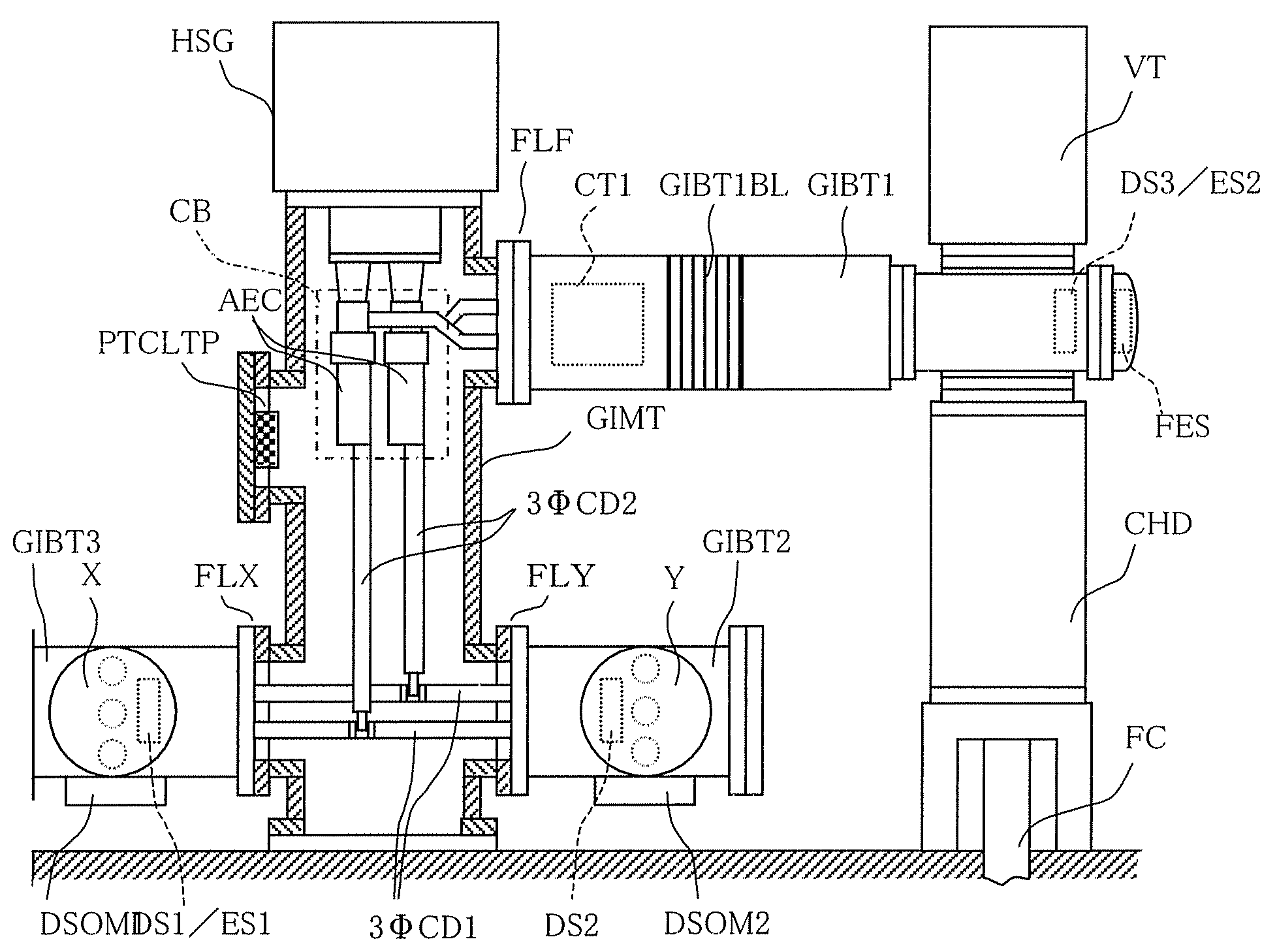
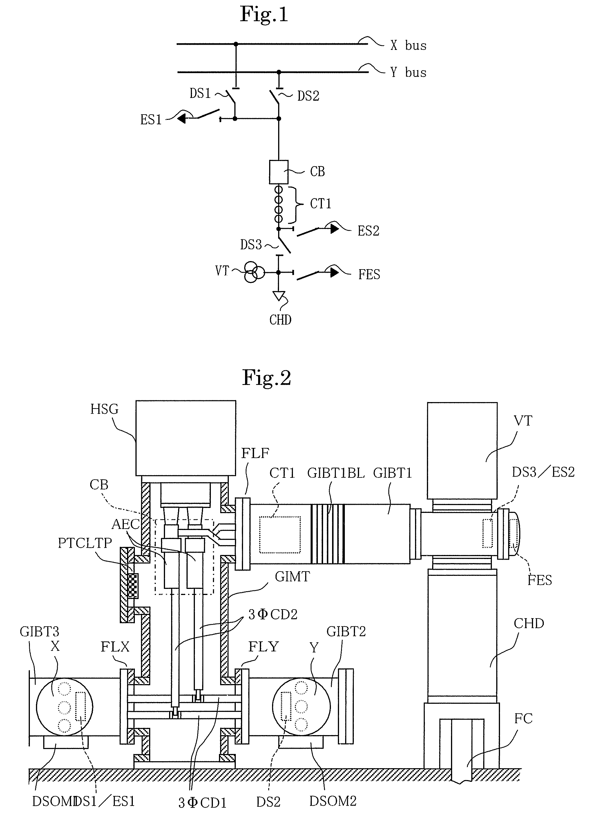
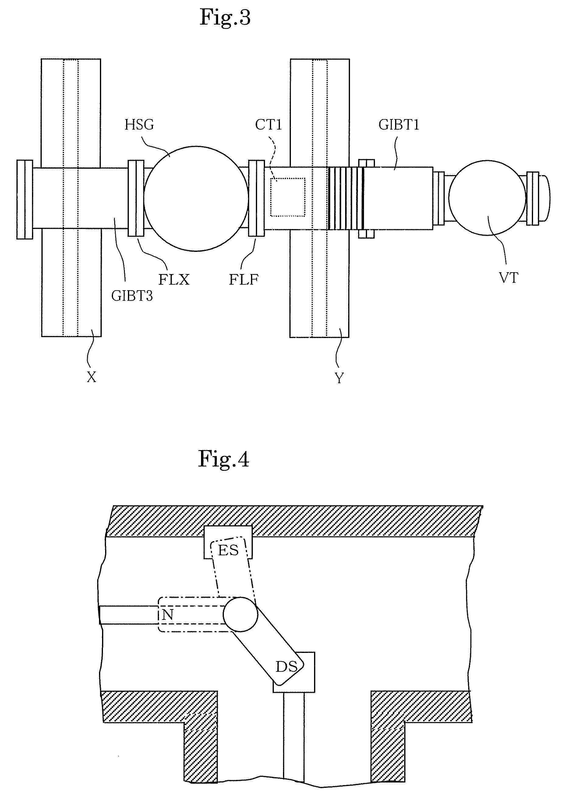
[0018]Embodiment 1 of the invention will be explained in reference to FIG. 1 through FIG. 4 as follows. FIG. 1 is a system diagram showing an example of a feeding system of a double bus type, FIG. 2 is a side view showing a portion of an example of a gas-insulated power apparatus in correspondence with the system diagram of FIG. 1 by a section, FIG. 3 is a plane view of the gas-insulated power apparatus shown in FIG. 2, FIG. 4 is a plane view showing a case of a switch DS / ES of a rotary type having a function of a disconnecting switch and a function of a grounding switch. Further, in FIG. 1 through FIG. 5, the same portions are attached with the same notations.

[0019]As shown by FIG. 1, an example of the feeding system of the double bus type in Embodiment 1 of the invention is the same as that in FIG. 21 mentioned above, a double buses X, Y are connected to a circuit breaker CB by way of a bus side disconnecting switch DS1, DS2. The bus side disconnecting switches DS1, DS2 on the sid...

embodiment 2

[0033]Embodiment 2 of the invention will be explained in reference to FIG. 5 and FIG. 6 as follows. FIG. 5 is a system diagram showing other example of a feeding system of a double bus type, FIG. 6 is a side view showing a portion of an example of a gas-insulated power apparatus in correspondence with the system diagram of FIG. 5 by a section. Further, in FIG. 5 and FIG. 6, portions the same as or corresponding to those of FIG. 1 through FIG. 4 are attached with the same notations, in explaining of Embodiment 2 as follows, a point different from FIG. 1 through FIG. 4 will mainly be explained and an explanation of the other will be spared.

[0034]As exemplified in FIG. 5, Embodiment 2 differs from Embodiment 1 in that a bus side current transformer CT2 commonly used for the buses X, Y is provided on a side of the buses X, Y of the circuit breaker CB.

[0035]As exemplified in FIG. 6, a physical arrangement of the bus side current transformer CT2 is provided at a surrounding of the second ...

embodiment 3

[0037]Embodiment 3 of the invention will be explained in reference to FIG. 7 and FIG. 8 as follows. FIG. 7 is a system diagram showing other example of a feeding system of a double bus type, and FIG. 8 is a side view showing an example of a gas-insulated power apparatus in correspondence with the system diagram of FIG. 7 by constituting a portion thereof by a section. Further, in FIG. 7 and FIG. 8, portions the same as or corresponding to those of FIG. 1 through FIG. 6 are attached with the same notations and in explaining Embodiment 3 as follows, a point different from FIG. 1 through FIG. 6 will mainly be explained and an explanation of the other will be spared.

[0038]As exemplified in FIG. 8, Embodiment 3 differs from Embodiment 1 in that the view ports PWX, PWY are provided on an upper side of a portion of intersecting the gas-insulated Y bus and the second gas-insulated branch pipe GIBT2 and an upper side of a portion of intersecting the gas-insulated X bus and the third gas-insu...


PUM


Abstract

A gas-insulated power apparatus comprising a vertically arranged gas-insulated circuit breaker included in a vertically arranged gas-insulated main tank, a first gas-insulated branch pipe connected to one side of an upper portion of the gas-insulated main tank substantially orthogonal to a direction of extending the gas-insulated main tank and leading out a feeder from a movable side of the gas-insulated circuit breaker, and a second and a third gas-insulated branch pipes which are respectively connected to both sides in a peripheral direction of a lower portion of the gas-insulated main tank substantially orthogonal to the direction of extending the gas-insulated main tank, one of which connects a fixed side of the gas-insulated circuit breaker to one gas-insulated Y bus of gas-insulated double buses and other of which connects the fixed side of the gas-insulated circuit breaker to other gas-insulated X bus of the gas-insulated double buses, respectively, by which a gas-insulated power apparatus having a structure in which although a width thereof is more or less widened, a height thereof is hardly changed and which is stable can be realized.

Description

TECHNICAL FIELD[0001]The present invention relates to a gas-insulated power apparatus for connecting a gas-insulated bus and a feeder by way of a gas-insulated circuit breaker.BACKGROUND ART[0002]According to a feeding system of a double bus type, for example, as shown by FIG. 21, double busses X, Y are connected to a circuit breaker CB by way of bus side disconnecting switches DS1, DS2. The bus side disconnecting switches DS1, DS2 on a side of the circuit breaker CB as well as the circuit breaker CB on a side of the circuit breakers DS1, DS2 are connected to a grounding switch ES1. A current transformer CT1, a disconnecting switch DS3, a voltage transformer VT, a grounding switch ES2 and a line side grounding switch FES are connected between a cable head CHD constituting a connection end of a feeder cable and the circuit breaker CB. As shown by FIG. 22, the respective apparatus are insulated by a gas and connected to each other to constitute a gas insulated power apparatus integrat...

Claims


Application Information

Patent Timeline
IPC IPC(8): H02B1/20H02B13/035
CPCH02B1/22H02B13/0352H02B5/06
Inventor OTSUKA, TAKUYASADAKUNI, HITOSHIFUJITA, DAISUKE
Owner MITSUBISHI ELECTRIC CORP
Why Eureka
Try Eureka