Medical image diagnostic device

a diagnostic device and medical imaging technology, applied in the direction of diagnostics, instruments, optical radiation measurement, etc., can solve the problems of imposing a heavy burden on the subject, ignoring the burden on the medical staff, and difficulty in adequately brightening the interior of the imaging part, so as to reduce the burden on the subject and the medical staff, and efficiently perform ct imaging and pet imaging.

Active Publication Date: 2009-06-18
TOSHIBA MEDICAL SYST CORP
View PDF10 Cites 21 Cited by
  • Summary
  • Abstract
  • Description
  • Claims
  • Application Information

AI Technical Summary

Benefits of technology

[0013]According to an aspect of the present invention, the interior of the imaging part is brightened and information about the progress of the imaging, etc. is provided for the subject placed within the imaging part with the field of vision being narrowly restricted. It results in freeing the subjects from the feeling of being enclosed, and getting them to undergo the imaging of medical images with a sense of reassurance, and thus a medical image diagnostic device that takes into account the standpoint of the subject is provided.
[0014]Moreover, because the imaging part of the X-ray CT device and the PET device is shared, and it is possible to sequentially align the subject, who is placed on the top surface of the bed, to each imaging position of the X-ray CT device and PET device, it is hence possible to efficiently perform CT imaging and PET imaging, thus reducing the burden on the subject and medical staff.
[0015]Moreover, because an illumination part and / or display part is provided, to avoid every imaging position by the X-ray CT device and the PET device, it is possible to definitely prevent causing any hindrance to the collection of image data using both devices.
[0016]Moreover, by utilizing the wall surfaces of the imaging part for a screen, including every position with the X-ray CT device and PET device, any hindrance to the collection of image data using both devices are prevented, broadening the range of the display.
[0017]Moreover, instructions can easily be given to the subjects to start and stop holding their breath, and imaging failures can be prevented. Moreover, it is possible to inform the subject of the time remaining until the end of the imaging, thus providing a sense of reassurance. Furthermore, by showing videos such as short films, even if the imaging takes a long time, subjects will not become bored, and it will be possible to get them to undergo imaging in a more relaxed manner.
[0018]Moreover, the illumination does not directly enter the eyes of the subject, there is no glare, and even with imaging that takes a long time, the subject can be kept still.

Problems solved by technology

In this case, X-ray CT devices and nuclear medical diagnosticdevices, even if they are within the same medical facility, are normally placed in separate imaging rooms, and imaging requires subjects tobe moved between the respective imaging rooms, placing a heavy burden on the subjects.
Also, regarding subjects with limited mobility, members of the medical staff have to place them on gurneys and transport them in that state to the respective imaging rooms, so one cannot ignore the burden on medical staff.
With the increase in the length of the imaging part of the hollow tube, it was difficult for illumination light from the exterior (in other words, from within the imaging room) to enter this location, so the interior of the imaging part turned out dark, and it was difficult to adequately brighten the interior of the imaging part, even if the illumination of the imaging room was brightened.
Also, between the imaging start point and reaching the completion point, this dark imaging part accounts for a large portion of the subject's field of vision, and so there was the problem of causing significant distress to the subject.
Furthermore, for the collection of image data by means of a PET device (hereafter, “PET imaging”), usually the time taken is around 30 minutes, and during this time, the subject must remain still, lying within the imaging part, thereby imparting distress and a sense of being enclosed.
Hence, disadvantageously, from both the perspective of the person performing the imaging and the perspective of the subject, the display mechanism's functions cannot be adequately utilized.

Method used


Image

  • Medical image diagnostic device
  • Medical image diagnostic device
  • Medical image diagnostic device

Examples


Embodiment Construction

[0029]The following is an explanation of one embodiment of the medical image diagnostic device according to the present invention.

[0030]Additionally, in these diagrams, the same parts have been marked with the same symbols.

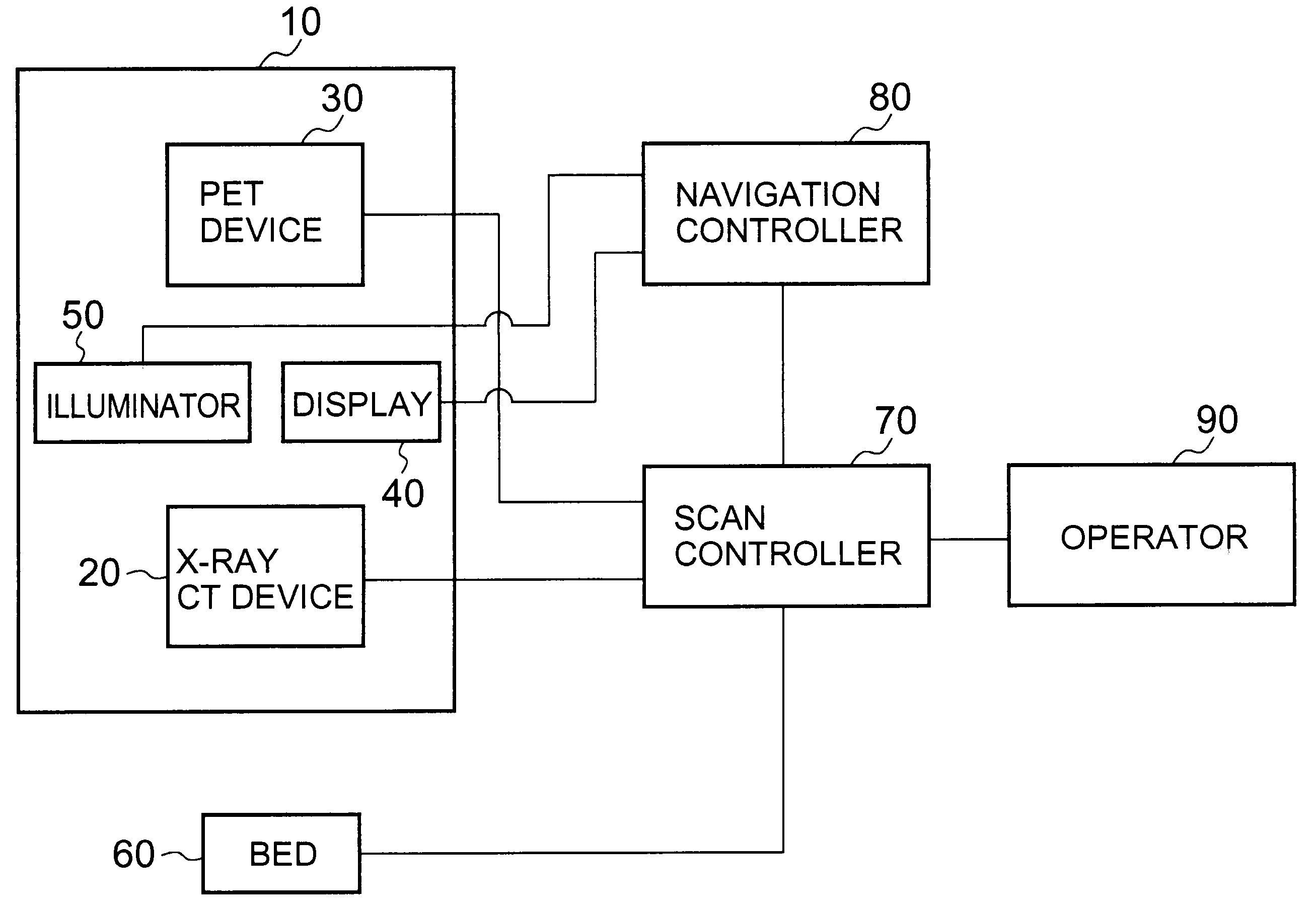
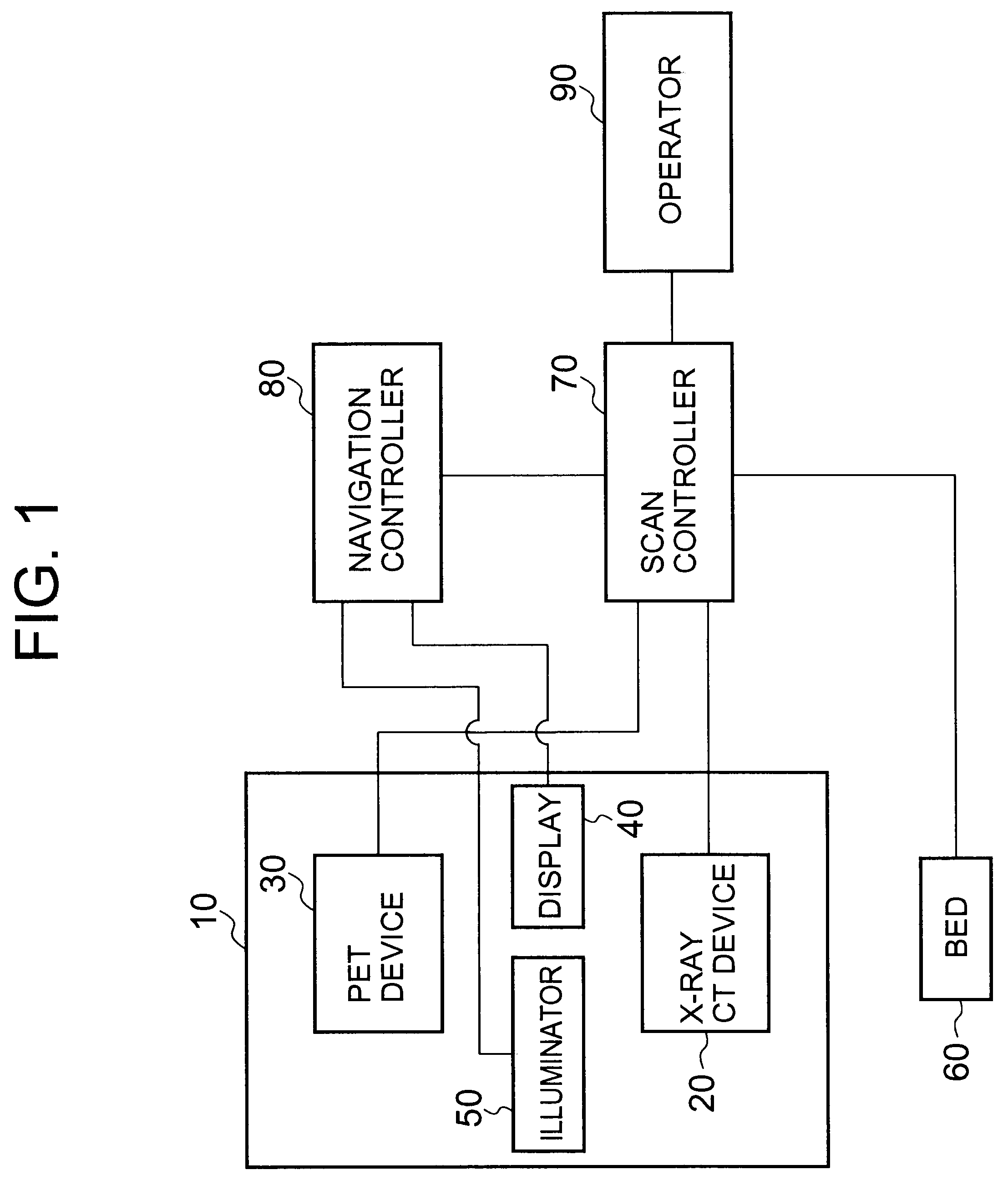
[0031]FIG. 1 is a schematic diagram showing the overall structure of one embodiment of a medical image diagnostic device. The medical image diagnostic device main unit 10 comprises an X-ray CT device 20 and a PET device 30, sharing a pedestal. The medical image diagnostic device main unit 10, which will be described again later, comprises an imaging part shared by an X-ray CT device 20 and a PET device 30, in which a display part 40 and an illumination part 50 are provided. Additionally, the medical image diagnostic device comprises a bed device 60, for sending a subject into the imaging part. Furthermore, it also comprises, among others, a scan controller 70, for controlling the X-ray CT device 20, the PET device 30 and the bed device 60, and it comprises a navig...


PUM


Abstract

In a medical image diagnostic device, wherein X-Ray CT devices and PET devices are longitudinally disposed, and which has a tubular imaging part for positioning a subject who is placed on the top surface of a bed and collecting image data, an illumination part is provided for producing a suitable level of brightness to the display part, which is for providing information to the subject without having to adopt every imaging position within the tubular imaging part, and to the imaging part.

Description

BACKGROUND OF THE INVENTION[0001]1. Field of the Invention[0002]The present invention relates to a medical image diagnostic device that comprises a combination of an X-ray CT device and a nuclear medical diagnostic device (for example, a PET device).[0003]2. Description of the Related Art[0004]Advances in medical image diagnostic devices have been remarkable, and they are used for early-stage discovery of diseases, confirmation of the location and shape / size of lesions, and the monitoring of treatment progress, thus contributing to the improvement of medical welfare. There are many types of these medical image diagnostic devices used, for example X-ray diagnostic devices, ultrasound diagnostic devices X-ray CT devices, magnetic resonance imaging devices, nuclear medical diagnostic devices, etc., according to the diagnostic objectives.[0005]Each of these medical image diagnostic devices has, respectively, different functional characteristics, and in recent times, by obtaining diagnos...

Claims


Application Information

Patent Timeline
Patent Type & Authority Applications(United States)
IPC IPC(8): H05G1/64A61B5/05
CPCA61B6/032A61B6/464A61B6/04A61B6/037
Inventor MATSUZAWA, YOHEINAKANO, MAKOTO
Owner TOSHIBA MEDICAL SYST CORP
Why Eureka
Try Eureka