
Door grating extension/contraction structure

Inactive Publication Date: 2009-06-25
WU SUNG TSUN
View PDF12 Cites 30 Cited by
  • Summary
  • Abstract
  • Description
  • Claims
  • Application Information

AI Technical Summary

Benefits of technology

[0005]A primary objective of the present invention is to provide a door grating extension / contraction structure comprising a plurality of bars interconnected to make a frame and an extension / contraction mechanism provided on at least two parallel ones of the bars. The extension / contraction mechanism is comprised of a combination of a telescopic tube set and a release assembly and is operated by depression and / or release of a release button of the release assembly to control the telescopic tube set so as to extend / contract the telescopic tube set for flexibly adjusting the frame for setting in door frames of different sizes, various stairways, or between walls to thereby facilitate the overall practicability and convenience.
[0006]Another objective of the present invention is to provide a door grating extension / contraction structure comprising an extension / contraction mechanism having a release assembly that is comprised of a release button, a transmission unit, and a pawl member, wherein the transmission unit provides a resilient interconnection between the components so that the location for arranging the release assembly is flexible to thereby enhance the convenience of the operation and use of the extendable frame and thus improving the overall practicability and convenience.
[0007]A further objective of the present invention is to provide a door grating extension / contraction structure comprising an extension / contraction mechanism having a telescopic tube set that is comprised of a movable rod that is set corresponding to and engageable with a pawl member of a release assembly and is configured with a slope so that one-way extension of a frame of the door grating can be realized without actuating a release button of the release assembly, making the use and operation of the extension / contraction mechanism more convenient and thus enhancing overall practicability and convenience.
[0008]Yet a further objective of the present invention is to provide a door frame extension / contraction structure comprising a combined assembly of a frame formed by interconnecting a plurality of bars and an extension / contraction mechanism provided on at least two parallel ones of the bars, with a corner section provided between adjacent bars for interconnection and further comprising a folding section arranged at joints between the bars to realize folding of a frame of the door grating for easy storage thereby enhancing overall practicability and convenience.

Problems solved by technology

Thus, family house often becomes a dangerous environment for young children.
Most injuries of the young children occur in the houses, including fall, tumble, and burning in for example kitchens.
Apparently, for young children or babies, who are of poor action controllability, have no recognition of dangerous conditions, have an increased ratio of head with respect to the whole body, and poor balance, family house is a place full of dangers.
Conventionally, a door grating is often comprised of steel bars that are welded to make a frame, of which the manufacturing costs are high and the size is fixed, lacking flexibility in applications.
However, the assembling and disassembling of the conventional combinative gratings are time- and labor-consuming.
Further, flexible adjustment of the frame size of the grating is still impossible.

Method used


Image

  • Door grating extension/contraction structure
  • Door grating extension/contraction structure
  • Door grating extension/contraction structure

Examples


Embodiment Construction

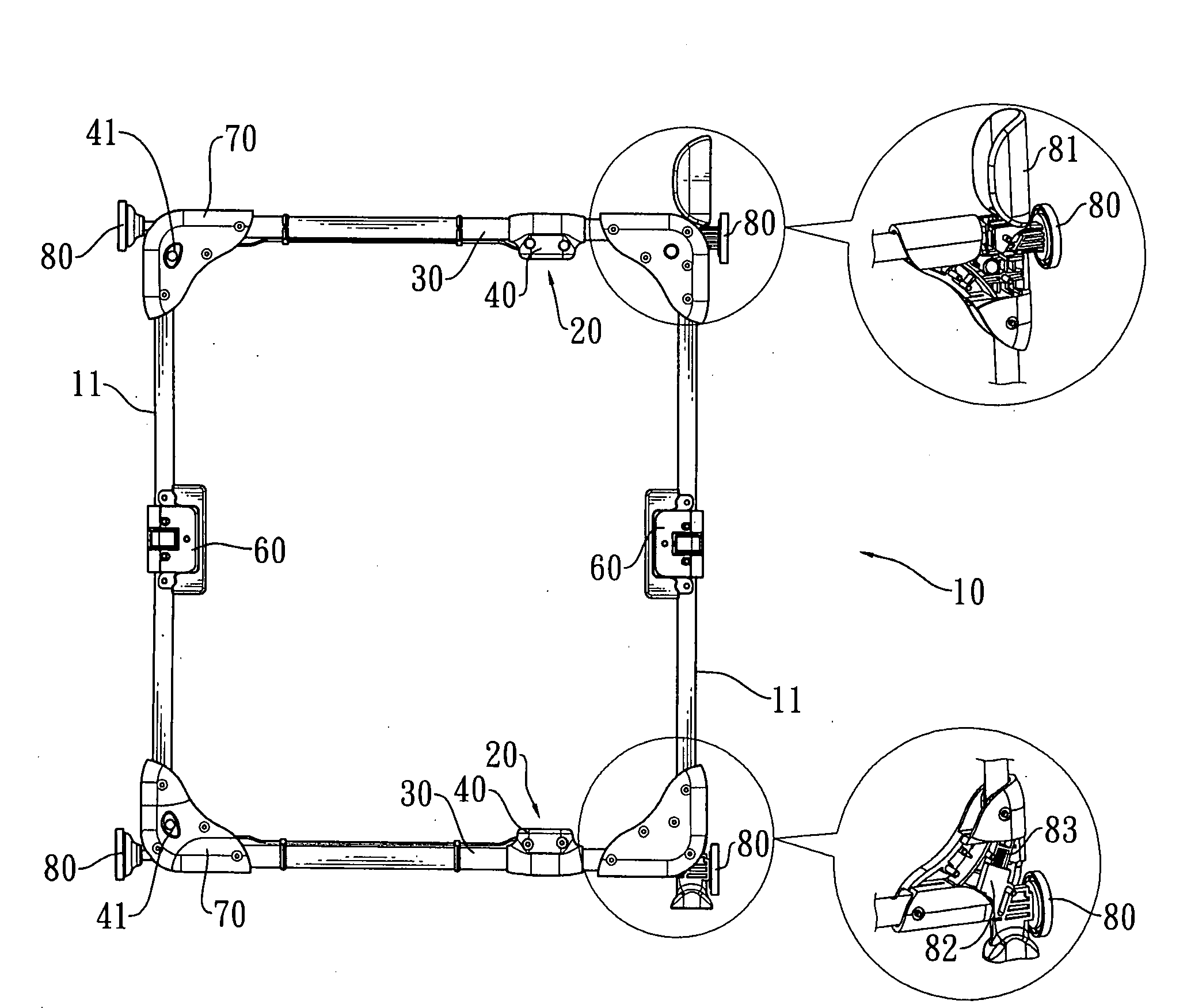
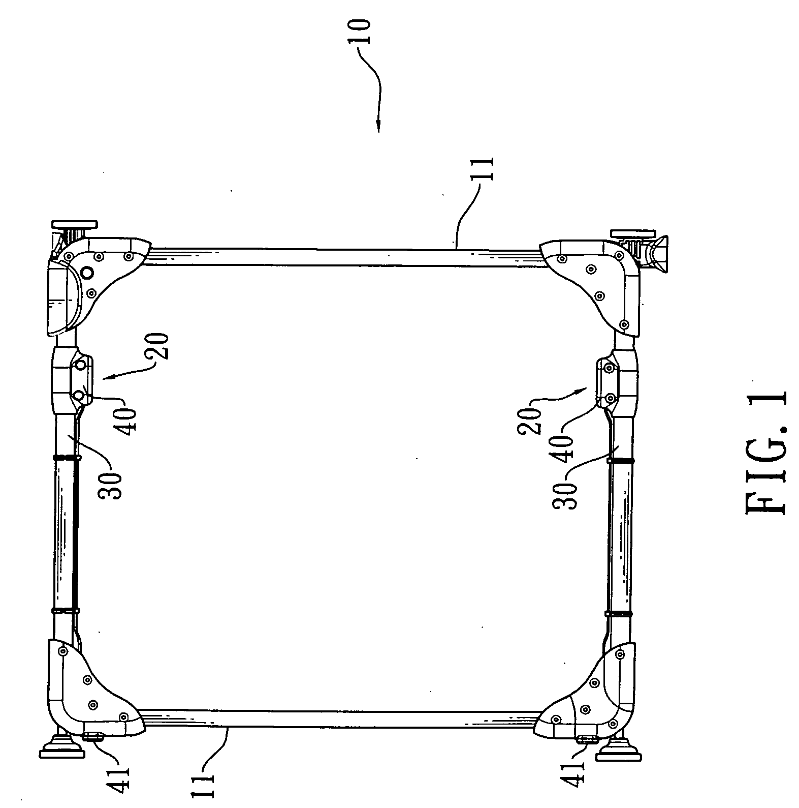
[0018]With reference to the drawings and in particular to FIG. 1, a door grating extension / contraction structure in accordance with the present invention comprises a frame 10 and an extension / contraction mechanism 20. The frame 10 consists of a plurality of bars 11 and is formed by interconnecting a plurality of bars 11. The two extension / contraction mechanisms 20 are respectively arranged on two parallel ones of the bars 11 of the frame 10 and each extension / contraction mechanism 20 is comprised of a telescopic tube set 30 and a release assembly 40.

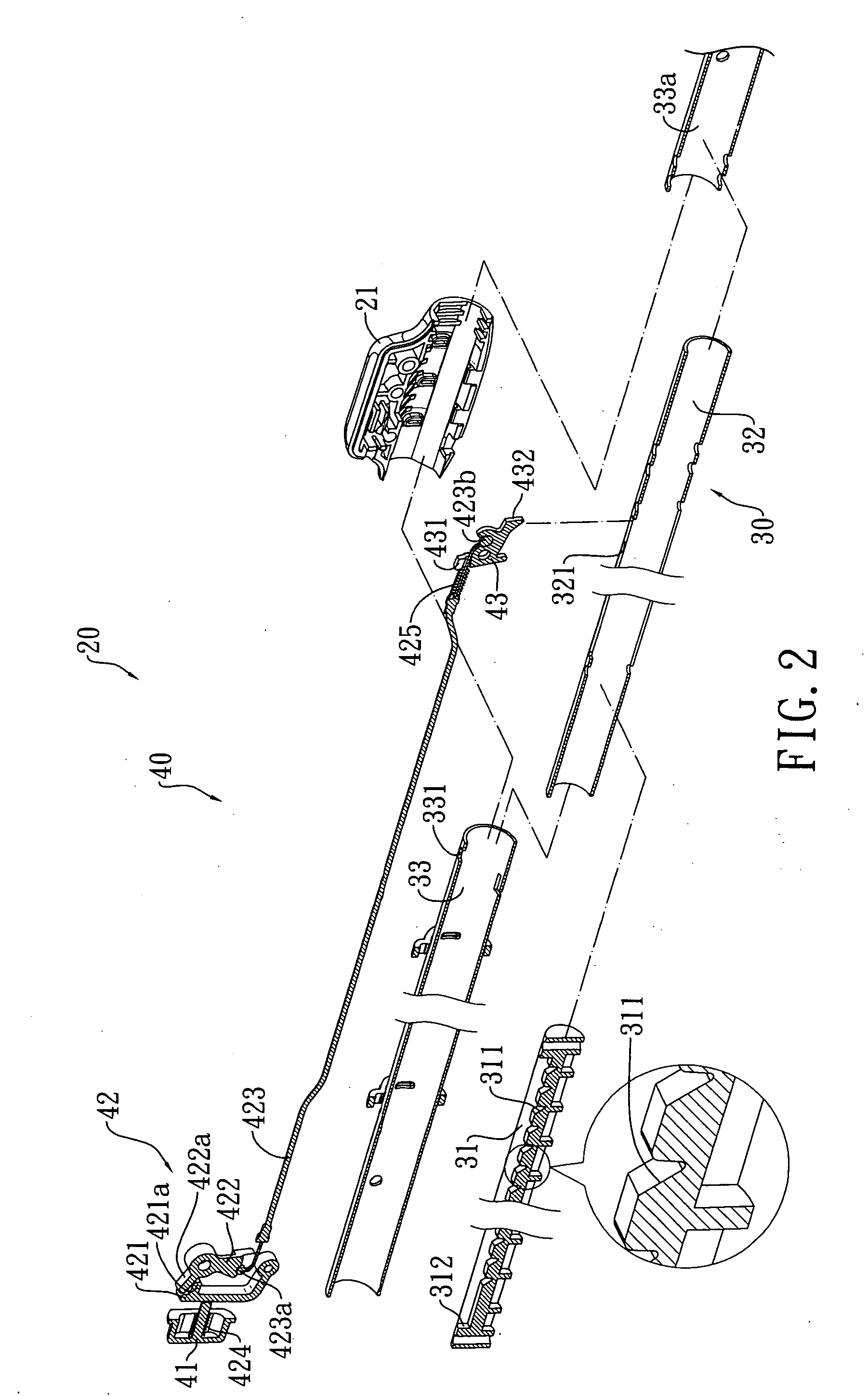
[0019]Referring to FIGS. 24, the telescopic tube set 30 of the extension / contraction mechanism 20 comprises a movable rod 31 and in the embodiment illustrated, the telescopic tube set 30 consists of an outer tube 33 and an inner tube 32, wherein the inner tube 32 is fit in the outer tube 33 and is movable within the outer tube 33. The movable rod 31 is received and coupled inside the inner tube 32 and the movable rod 31 forms a plurality...


PUM


Abstract

A door grating extension / contraction structure includes a frame and an extension / contraction mechanism. The frame is comprised of a plurality of bars. The extension / contraction mechanism is mounted to two parallel bars of the frame and is comprised of a telescopic tube set and a release assembly, wherein the telescopic tube set comprises a movable rod and the release assembly is coupled to the telescopic tube set and comprises a release button, a pawl member, and a transmission unit. The release button is coupled with the transmission unit and the transmission unit is coupled with the pawl member to form a resilient interconnection. The pawl member corresponds to and selectively forms an adjustable engagement with the movable rod of the telescopic tube set. The release button is operative to control engagement and disengagement between the pawl member and the movable rod, whereby the extension / contraction mechanism that is coupled to the frame can realize one-way or two-way extension / contraction to provide the door grating extension / contraction structure.

Description

FIELD OF THE INVENTION[0001]The present invention relates to a door grating extension / contraction structure, and in particular to a door grating comprised of a frame formed by interconnecting a plurality of bars, of which at least two parallel ones are provided with an extension / contraction mechanism, which comprises a combination of a telescopic tube set and a release assembly to realize extension / contraction of the telescopic tube set for flexibly adjusting an overall length of the frame for setting in door frames of different sizes, various stairways, or between walls and thus applicable to a door barrier grating structure or the likes.BACKGROUND OF THE INVENTION[0002]Indoor decoration of family housing only puts the needs of adults into consideration and such indoor decoration remains unchanged even after the birth of new born babies. Thus, family house often becomes a dangerous environment for young children. Most injuries of the young children occur in the houses, including fa...

Claims


Application Information

Patent Timeline
IPC IPC(8): E06B9/02
CPCE06B2009/002E06B9/02
Inventor WU, SUNG-TSUN
Owner WU SUNG TSUN
Learn More