Linear Actuator

a linear actuator and actuator technology, applied in the field of linear actuators, can solve the problems of instable and imprecise non-synchronous actuators, and achieve the effect of reducing the extending and retracting time of linear actuators

Inactive Publication Date: 2009-06-25
HIWIN MIKROSYST
View PDF5 Cites 4 Cited by
  • Summary
  • Abstract
  • Description
  • Claims
  • Application Information

AI Technical Summary

Benefits of technology

[0015]The primary objective of the present invention is to provide a linear actuator which can be extended or retracted synchronously by the relative motion of a screw and a pushing post by cooperating with a plurality of guiding wheels and pulling members, so as to reduce the extending and retracting time of the linear actuator.
[0016]The second objective of the present invention is to provide a linear actuator which can prevent the outer pipe, the middle pipe and the inner pipe from rotating by a plurality of arc-shaped portions and guiding portions, so as to improve the stability and precision of the linear motion of the linear actuator.
[0017]The third objective of the present invention is to provide a linear actuator which can control the tension of the first pulling member and the second pulling member by adjusting the height of two positioning rods by two adjustment screws.

Problems solved by technology

As a result, the conventional nonsynchronous actuator is instable and is imprecise.

Method used


Image

  • Linear Actuator
  • Linear Actuator
  • Linear Actuator

Examples


Embodiment Construction

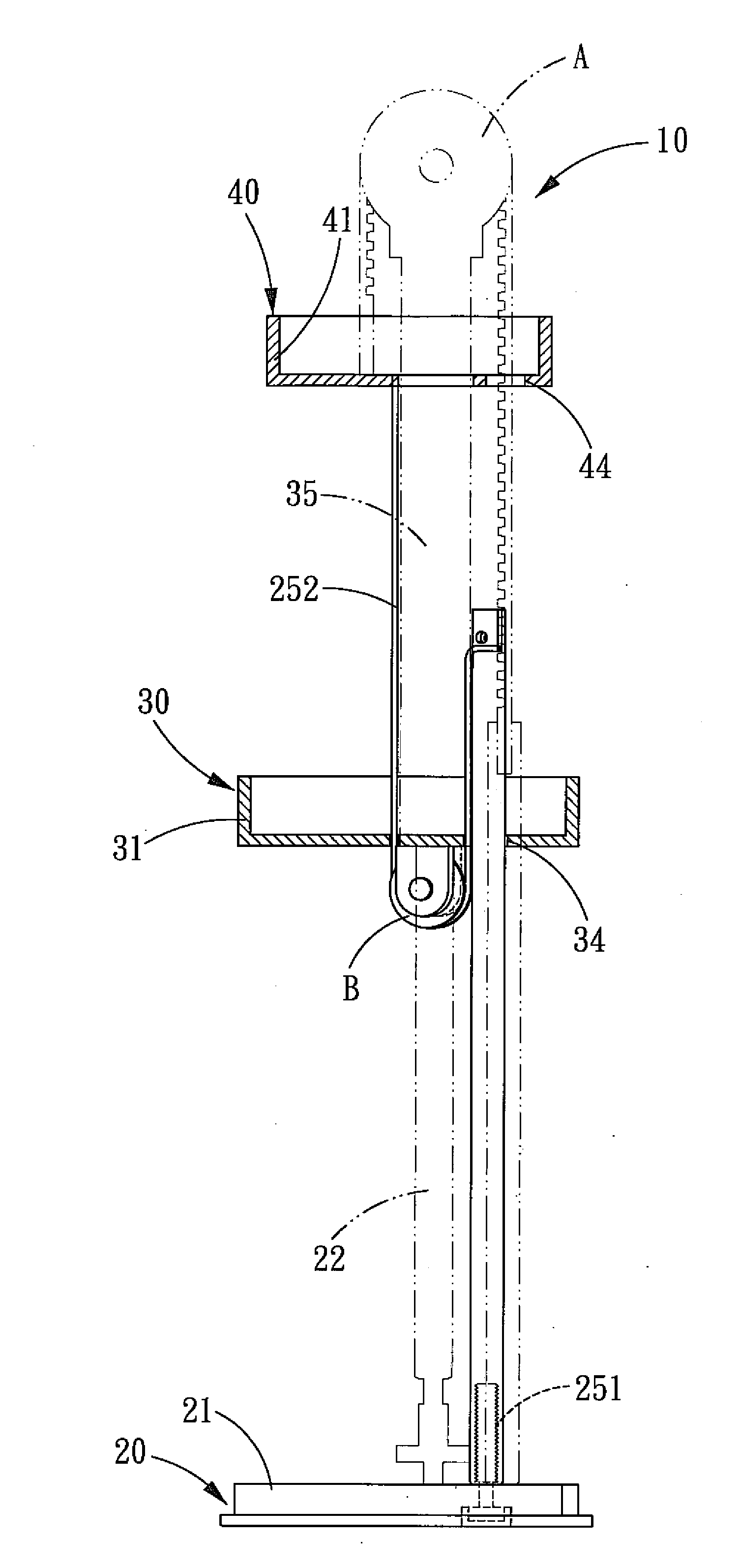
[0027]Referring to FIGS. 4-8, a linear actuator 10 in accordance with the present invention comprises an outer pipe 20, a middle pipe 30 and an inner pipe 40.

[0028]The outer pipe 20 has an approximately triangle-shaped cross section. A periphery of the outer pipe 20 is formed with three spaced-apart arc-shaped portions 201 and three guiding portions 202 that are alternatively arranged in such a manner that one arc-shaped portion 201 is located between two guiding portions 202, or one guiding portion 202 is located between two arc-shaped portions 201. The outer pipe 20 is a penetrated hollow member. One end of the outer pipe 20 is disposed with a cover 21, and a screw 22 is axially and pivotally disposed on the cover 21. One end of the screw 22 is radially formed with a gear 23, and the gear 23 is dynamically connected to a motor by a belt. A first positioning rod 24 and a second positioning rod 25 are axially locked to the cover 21 by a first adjustment screw 241 and a second adjust...


PUM


Abstract

A linear actuator orderly comprises an inner pipe, a middle pipe and an outer pipe, and the pipes are pivotally connected with each other. Each pipe is formed with at least three arc-shaped portions and three guiding portions, and the pipes abut against each other. The outer pipe is axially formed with a screw and two positioning rods that are passed through the middle pipe and the inner pipe, respectively. One end of each positioning rod is fixed with a pulling member, and one end of each pulling member is fixed to the inner pipe. The middle pipe is axially formed with a pushing post threaded with the screw. The pushing post and the middle pipe are pivotally disposed with a guiding wheel for rolling the pulling members, respectively. The pipes can be moved by the relative motion of the screw and the pushing post by cooperating with the guiding wheels and the pulling members, such that the pipes can be extended or retracted synchronously.

Description

BACKGROUND OF THE INVENTION[0001]1. Field of the Invention[0002]The present invention relates to an actuator, and more particularly to a linear actuator.[0003]2. Description of the Prior Art[0004]The use of actuators is quite extensive, and one kind of the actuators is the nonsynchronous actuator. Referring to FIG. 1, a conventional nonsynchronous actuator 90 comprises a base 91, a first cylinder 92, a second cylinder 93, a third cylinder 94, a motor 95, a first screw 96, a second screw 97 and a third screw 98.[0005]The first cylinder 92 includes a containing space 921, and one end of the first cylinder 92 is fixed to a top side of the base 91.[0006]The second cylinder 93 includes a containing space 931 and is pivotally disposed in the containing space 921 of the first cylinder 92.[0007]The third cylinder 94 includes a containing space 941 and is pivotally disposed in the containing space 931 of the second cylinder 93. The motor 95 is fixed to one end of the third cylinder 94.[0008]...

Claims


Application Information

Patent Timeline
Patent Type & Authority Applications(United States)
IPC IPC(8): F16H29/02
CPCF16H19/0663Y10T74/18664F16H25/2056
Inventor CHUO, YUNG-TSAI
Owner HIWIN MIKROSYST
Why Eureka
Try Eureka