

High-stability video triggering method and digital oscilloscope
A high-stability, video-based technology, applied in the direction of TV, color TV, color TV parts, etc., can solve the problem of unstable video triggering, avoid application limitations, reduce the interference of superimposed noise, and improve accuracy and stability effects
- Summary
- Abstract
- Description
- Claims
- Application Information
AI Technical Summary
Problems solved by technology
Method used
Image

Examples
Embodiment 1
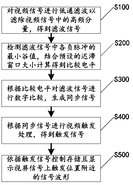
[0033] Please refer to figure 1 , the present application discloses a video triggering method with high stability, including steps S100-S500, which will be described respectively below.
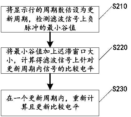
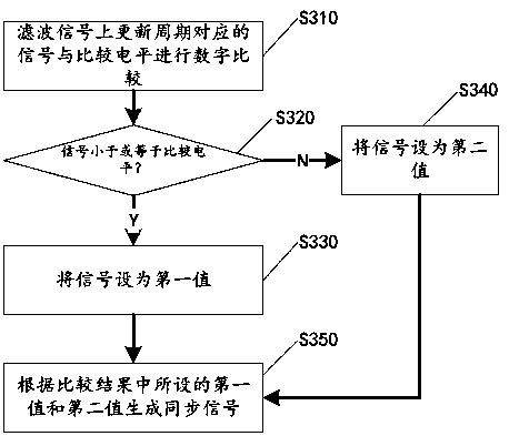
[0034] Step S100, acquire and low-pass filter the video signal to filter out the high-frequency components in the video signal to obtain a filtered signal; the high-frequency components are used to carry the brightness of each display line in each frame of video picture corresponding to the video signal information and colorimetric information.
[0035] It should be noted that the video signal here refers to TV signal, still image signal and visible TV image signal, which should be the digitized form of any standard (NTSC, PAL and SECAM) analog video signal. Several samples are obtained, so that the video signal can be low-pass filtered in a digital processing manner.
[0036] For example Figure 5 and Figure 6 The NTSC video signal shown in , the signal type is a composite video signal,...
Embodiment 2
[0063] Please refer to Figure 10 , on the basis of the video trigger method disclosed in Embodiment 1, the present application also discloses a digital oscilloscope, including a signal input channel 11 , a processing circuit 12 , a memory 13 and a display 14 .
[0064] The signal input channel 11 is formed with an input interface on the interface panel of the digital oscilloscope, and the input interface can be connected to an external analog video signal line, and the signal input channel 11 is mainly used for converting an externally input analog video signal into a digital video signal. And the digitized video signal is sent to the processing circuit 12 for video trigger processing.
[0065] The processing circuit 12 is connected to the signal input channel 11, and is used for controlling, storing and displaying the signal waveform near the trigger position on the video signal according to the video trigger method disclosed in the first embodiment. Specifically, the proce...
PUM
 Abstract
Description
Claims
Application Information