Oven controlled crystal oscillator and manufacturing method thereof

a technology of crystal oscillator and manufacturing method, which is applied in the direction of oscillator stabilization, electrical equipment, oscillator generator, etc., can solve the problems of increasing both costs and manufacturing process complexity, poor temperature control accuracy, and significant increase in component volume and power consumption, so as to improve temperature control precision and small volume

Active Publication Date: 2015-04-28
GUANGDONG DAPU TELECOM TECH CO LTD
View PDF9 Cites 2 Cited by
  • Summary
  • Abstract
  • Description
  • Claims
  • Application Information

AI Technical Summary

Benefits of technology

[0008]The present invention provides an Oven Controlled Crystal Oscillator and a manufacturing method thereof, for the purpose of improving the temperature control precision while maintaining a relative small volume of the Oven Controlled Crystal Oscillator.
[0018]By mounting the signal generating element in the groove disposed on the PCB, on one hand, the thickness of the Printed Circuit Board between the heating device and the signal generating element is decreased to improve the heating effect, and on the other hand, the signal generating element is partially or entirely enclosed by the groove to achieve an improved heat-insulating property, and the impact of the external temperature change on the temperature of the signal generating element is reduced, thereby improving the precision and stability of the temperature control of a crystal oscillator circuit. Furthermore, thanks to the groove disposed on the PCB, the volume of the Oven Controlled Crystal Oscillator is further decreased, which brings about advantages of a small volume and a high temperature control precision.

Problems solved by technology

Such temperature control manner is poor in temperature control precision in that if the ambient temperature changes, a part of the crystal resonator 20 that is farthest from the heating source is likely to be influenced by the ambient temperature change.
However, this manner introduces additionally the metallic thermal conductive chamber and the outer PCB for the purpose of the heating conducted indirectly via the metallic thermal conductive chamber, so that both the component volume and power consumption is significantly increased, and both costs and manufacturing process complexity is increased accordingly.

Method used


Image

  • Oven controlled crystal oscillator and manufacturing method thereof
  • Oven controlled crystal oscillator and manufacturing method thereof
  • Oven controlled crystal oscillator and manufacturing method thereof

Examples


Embodiment Construction

[0028]The technical solutions of the present invention are further described below in conjunction with the drawings and specific embodiments. It may be understood that the specific embodiments described herein are only used to explain but not to limit the present invention. Furthermore, it should be noted that parts and steps relevant to the present invention are illustrated in the drawings only for the convenience of description.

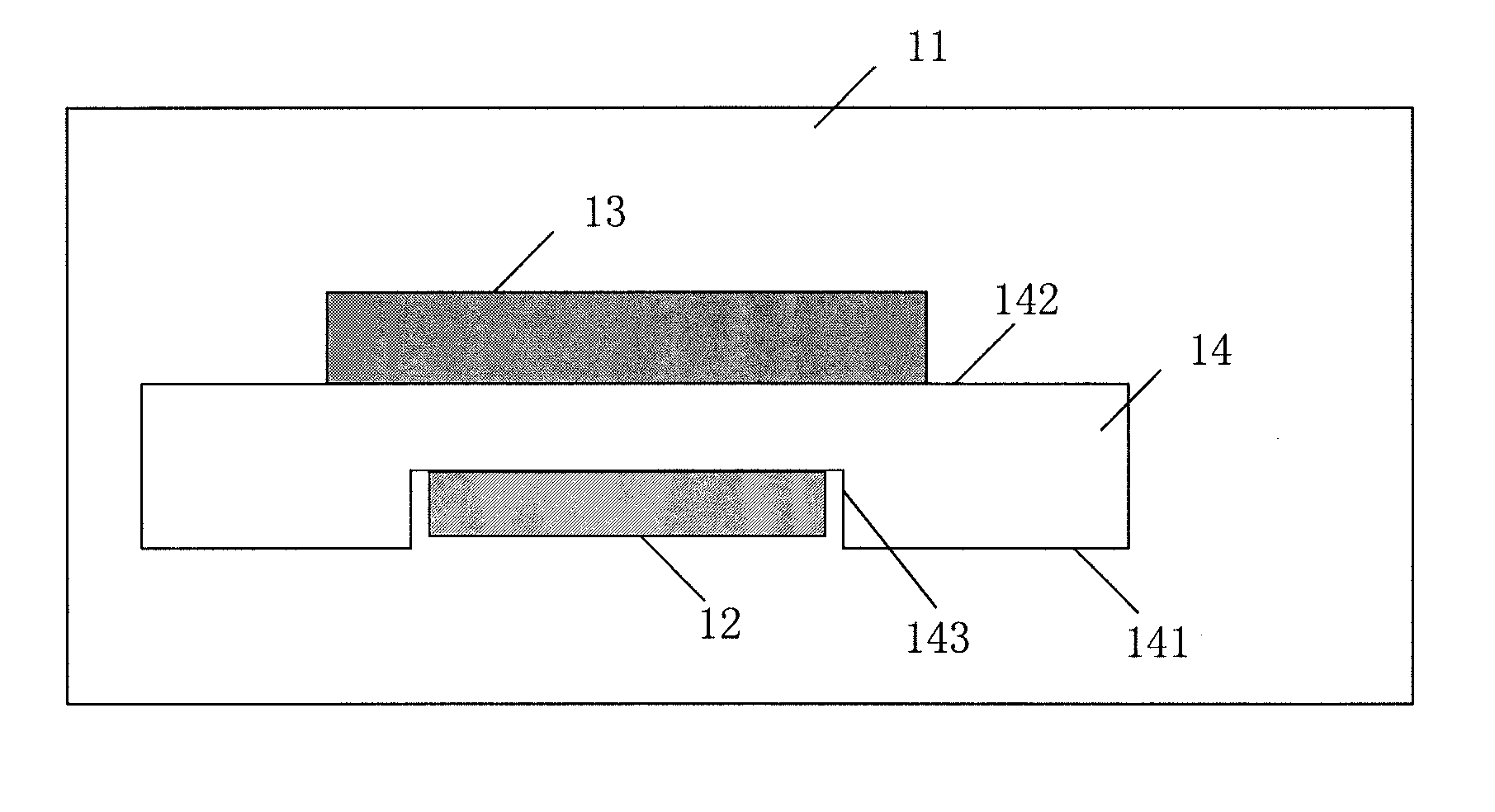
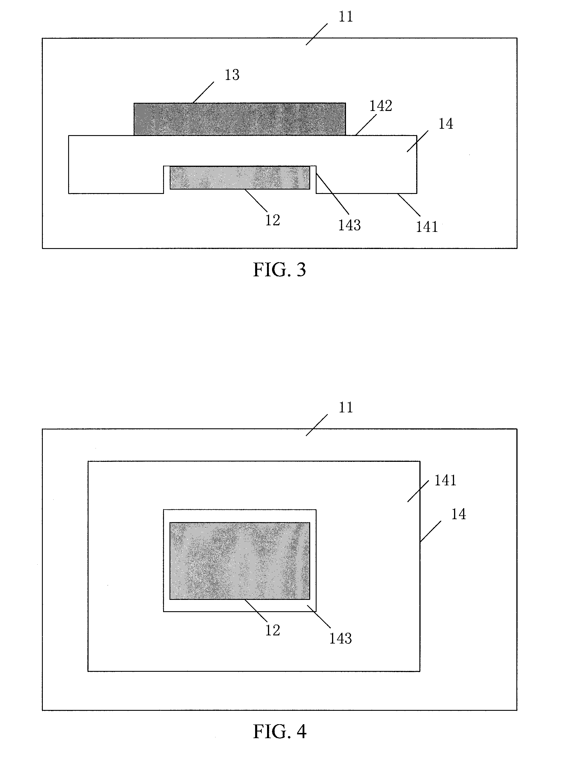
[0029]FIG. 3 is a schematic sectional view of an Oven Controlled Crystal Oscillator according to a first example embodiment. FIG. 4 is a schematic top view of the Oven Controlled Crystal Oscillator according to the first example embodiment. As shown in FIGS. 3 and 4, the Oven Controlled Crystal Oscillator includes a thermostatic bath 11, a signal generating element 12, a heating device 13, and a Printed Circuit Board 14.

[0030]The signal generating element 12 is used for generating a signal of a certain frequency.

[0031]The heating device 13, the PCB 14 and t...


PUM

PropertyMeasurementUnit
frequencyaaaaaaaaaa
thermal conductiveaaaaaaaaaa
thicknessaaaaaaaaaa

Abstract

The present invention discloses an Oven Controlled Crystal Oscillator and a manufacturing method thereof. The Oven Controlled Crystal Oscillator comprises a thermostatic bath, a heating device, a PCB and a signal generating element, where the signal generating element is used for generating a signal of a certain frequency, the heating device, the PCB and the signal generating element are mounted in the thermostatic bath, the signal generating element is mounted in a groove formed on one side of the PCB, while the heating device is mounted against the other side of the PCB that is opposite to the groove. The signal generating element may be a passive crystal resonator or an active crystal oscillator. The Oven Controlled Crystal Oscillator according to the invention is advantageous for a small volume and a high temperature control precision.

Description

CROSS-REFERENCE TO RELATED APPLICATIONS[0001]This application is the national stage entry of International Application No. PCT / CN2012 / 084869, entitled “OVEN CONTROLLED CRYSTAL OSCILLATOR AND MANUFACTURING METHOD THEREOF,” filed on Dec. 6, 2012, which claims the right of priority based on Chinese Patent Application No. 201210438939.7 entitled “CONSTANT TEMPERATURE CONTROL CRYSTAL OSCILLATOR AND MANUFACTURING METHOD THEREOF” filed on Nov. 6, 2012, which is incorporated herein by reference and assigned to the assignee herein.TECHNICAL FIELD[0002]The present invention relates to crystal oscillator technologies, in particular to an Oven Controlled Crystal Oscillator and a manufacturing method thereofTECHNICAL BACKGROUND[0003]A quartz crystal oscillator is very precise and stable, and has been widely used in various oscillating circuits for a color TV set, a computer and a remote controller, as well as used in a communication system as a frequency generator, to generate a clock signal for...

Claims


Application Information

Patent Timeline
Patent Type & Authority Patents(United States)
IPC IPC(8): H03L1/04H05K3/30
CPCH03L1/04H05K3/30Y10T29/4913
Inventor LIU, CHAOSHENG
Owner GUANGDONG DAPU TELECOM TECH CO LTD
Why Eureka
Try Eureka