Socket For Fenestrated Tubular Prosthesis

Inactive Publication Date: 2009-06-25
COOK INC +1
View PDF27 Cites 55 Cited by
  • Summary
  • Abstract
  • Description
  • Claims
  • Application Information

AI Technical Summary

Benefits of technology

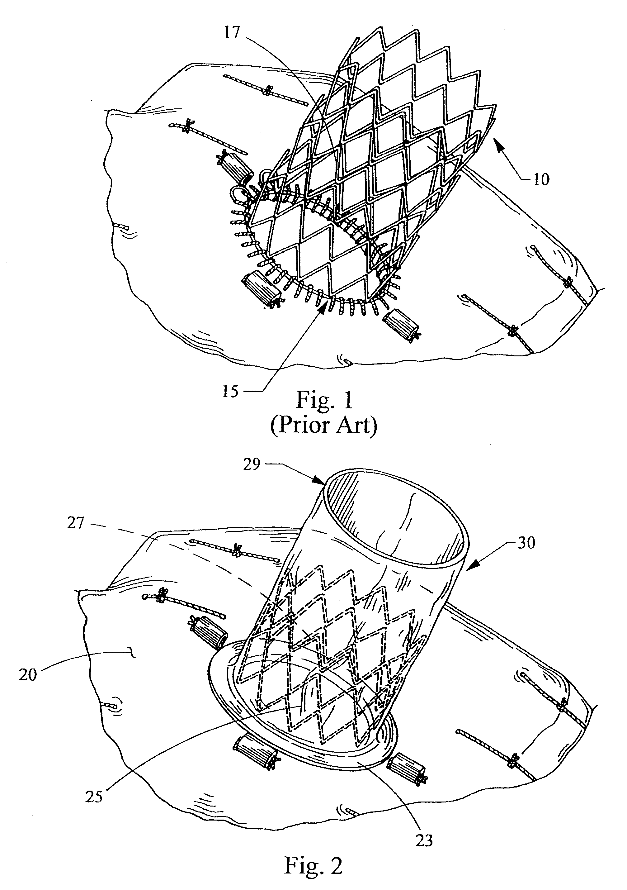
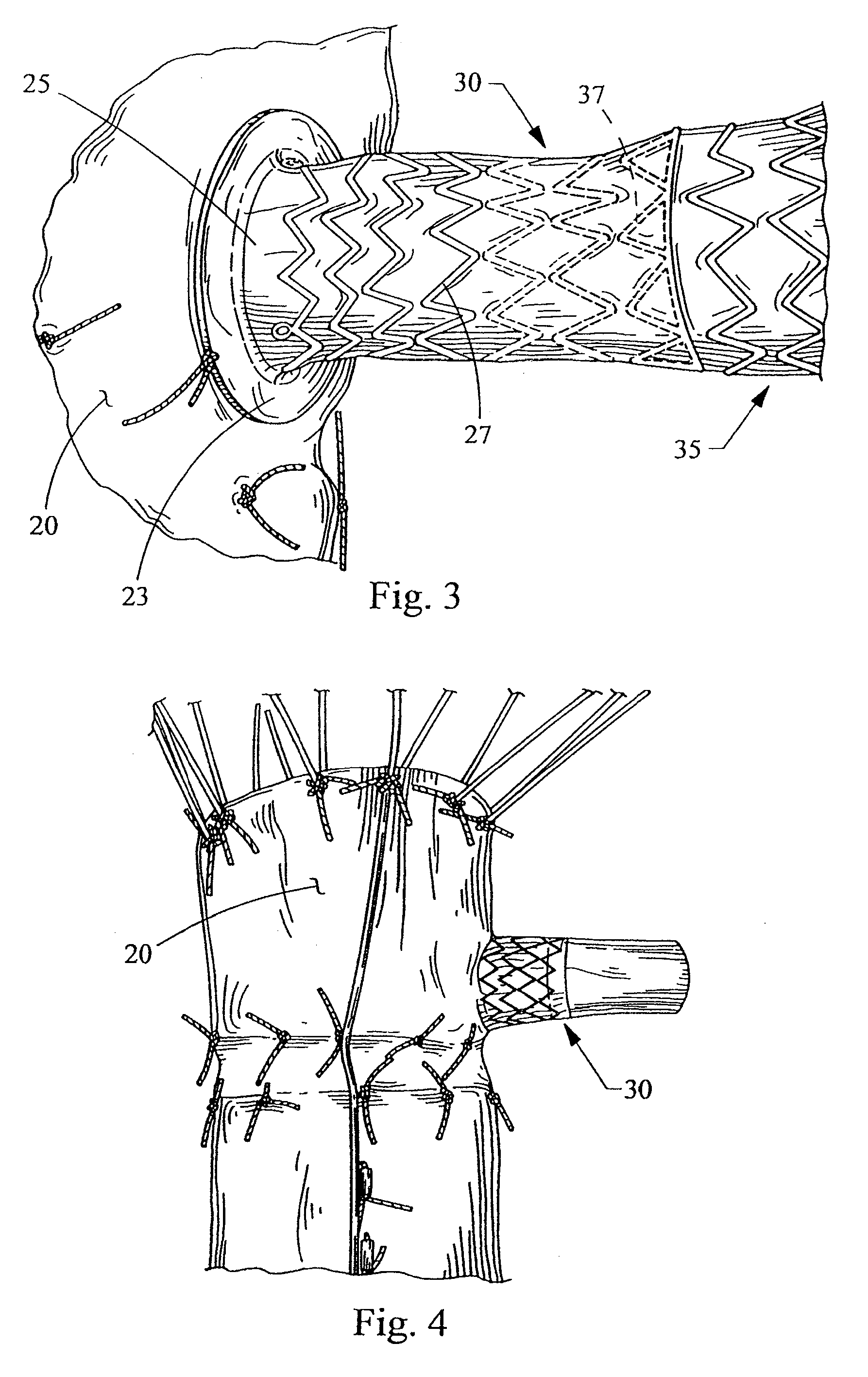
[0013]In yet another aspect of the present invention, the socket may be made from polyurethane, expanded polytetratfluoroethylene (ePTFE), or any other polymer that provides sufficient elasticity, deformability, and biocompatibility. Reinforcing elements, such as nitinol or PET fibers, may be imbedded in the socket to adjust the radial and longitudinal stiffness. Radiopaque markers, such as gold, may be placed within the socket to assist in plac

Problems solved by technology

Since the arterial tree is constantly under pulsatile motion due to hemodynamic and anatomical loads, the deployed bare metal stent is very often under severe and complicated loading conditions (bending, radial pulsation, shearing, etc.) This must be borne entirely through the narrow interface presented by the ring.
Furthermore, there is normally considerable plastic deformation induced to the stent during current deployment techniques which can lead to localized fracture of the stent that negates the alignment function of the fenestration stent.
The difficulty in providing adequate renal support using either covered or bare metal stents is the narrow interaction zone between the infra-renally placed stent and the fenestrated stent graft.
However, due to the relative rigidity of the fixed diameter rings and the inextensibility of the graft, the diameter of the covered bridging socket may not exceed about a millimeter

Method used


Image

  • Socket For Fenestrated Tubular Prosthesis
  • Socket For Fenestrated Tubular Prosthesis
  • Socket For Fenestrated Tubular Prosthesis

Examples


Example

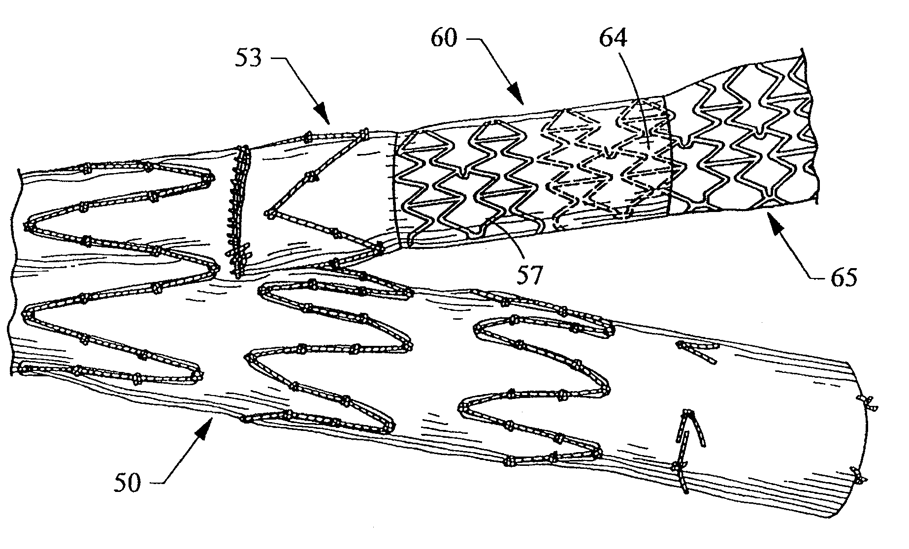
DETAILED DESCRIPTION OF THE DRAWINGS AND THE PREFERRED EMBODIMENTS

[0030]Unless defined otherwise, all technical and scientific terms used herein have the same meaning as commonly understood to one of ordinary skill in the art to which this invention belongs.

[0031]Throughout this specification, when discussing the application of this invention to the aorta, the term distal, with respect to a prosthesis, is intended to refer to the end of the prosthesis furthest away in the direction of blood flow from the heart, and the term proximal is intended to mean the end of the prosthesis that, when implanted, would be nearest to the heart.

[0032]The term “graft or graft material” means a generally cannular or tubular member which acts as an artificial vessel or prosthesis. A graft by itself or with the addition of other elements, such as structural components, may be an endoluminal prosthesis. The graft comprises a single material, a blend of materials, a weave, a laminate, or a composite of t...


PUM


Abstract

A stent graft adapted to telescopically receive a secondary stent graft having an evertible, elastic socket communicating with an opening in the stent graft. The socket comprises an elastic wall that forms a lumen with a stent at least partially encased within the wall. The socket may be adapted for use with stent grafts for implantantation in an aneurysm.

Description

CROSS-REFERENCE TO RELATED APPLICATION[0001]The present application claims priority to Provisional Application Ser. No. 61 / 008,947, filed Dec. 21, 2007, which is a continuation-in-part of the co-pending application claiming priority to Application Ser. No. 60 / 962,109, filed Jul. 26, 2007.TECHNICAL FIELD[0002]This invention relates to a medical device for implantation within the human or animal body for the treatment or repair of aortic aneurysms.BACKGROUND[0003]One of the primary functions of the fenestrated stent graft with bridging stent is to maintain patency of the renal arteries even though the proximal end of the stent-graft extends beyond the renal arteries. Conventionally, a balloon expandable bare stent is deployed into the renal arteries through the fenestration in the main graft to assure alignment is maintained while the stent-graft is being delivered (e.g., manipulated) and continues to maintain patency post-procedure. Fenestrated stent grafts usually use a sutured rein...

Claims


Application Information

Patent Timeline
IPC IPC(8): A61F2/06
CPCA61F2/07A61F2002/061A61F2002/067A61F2250/0036A61F2220/005A61F2250/0098A61F2/89A61F2002/072A61F2002/075A61F2250/0039
Inventor BIGGS, DAVID P.SUN, JICHAOLEEWOOD, ALAN R.
Owner COOK INC
Why Eureka
Try Eureka