Braced frame force distribution connection

a technology of braced frame and force distribution, which is applied in the direction of girders, building repairs, shock-proofing, etc., can solve the problems of life loss, complex assessment, and collapse of structur

Inactive Publication Date: 2009-07-02
SEISMIC STRUCTURAL DESIGN ASSOCS
View PDF10 Cites 49 Cited by
  • Summary
  • Abstract
  • Description
  • Claims
  • Application Information

AI Technical Summary

Problems solved by technology

These assessments are compounded in complexity when considering loads for wind and seismic events, and determining the forces, stresses, and strains.
Under high seismic or wind loading or even from repeated exposure to milder loadings, the connections in the structure may fail, possibly resulting in the collapse of the structure and the loss of life.
The presence of these gusset plates, which may be typically either bolted or welded to the joined members, causes the structure members to be rigidly joined so that the structural frame becomes, in essence, a braced-moment frame which results in unintentional overloading of the frame members (Richard 1986).
(2004) demonstrate that stiff beam-column-brace connections attract large force and moment demands, which can lead to high moments and shears in the beams and columns.
These unintentional high moments and shears in the joined members of the braced frame can result in premature fracture modes of the structural members when the frame is subjected to the design gravity, seismic, and wind loadings because these forces are not considered in the frame design.
As previously s

Method used


Image

  • Braced frame force distribution connection
  • Braced frame force distribution connection
  • Braced frame force distribution connection

Examples


Embodiment Construction

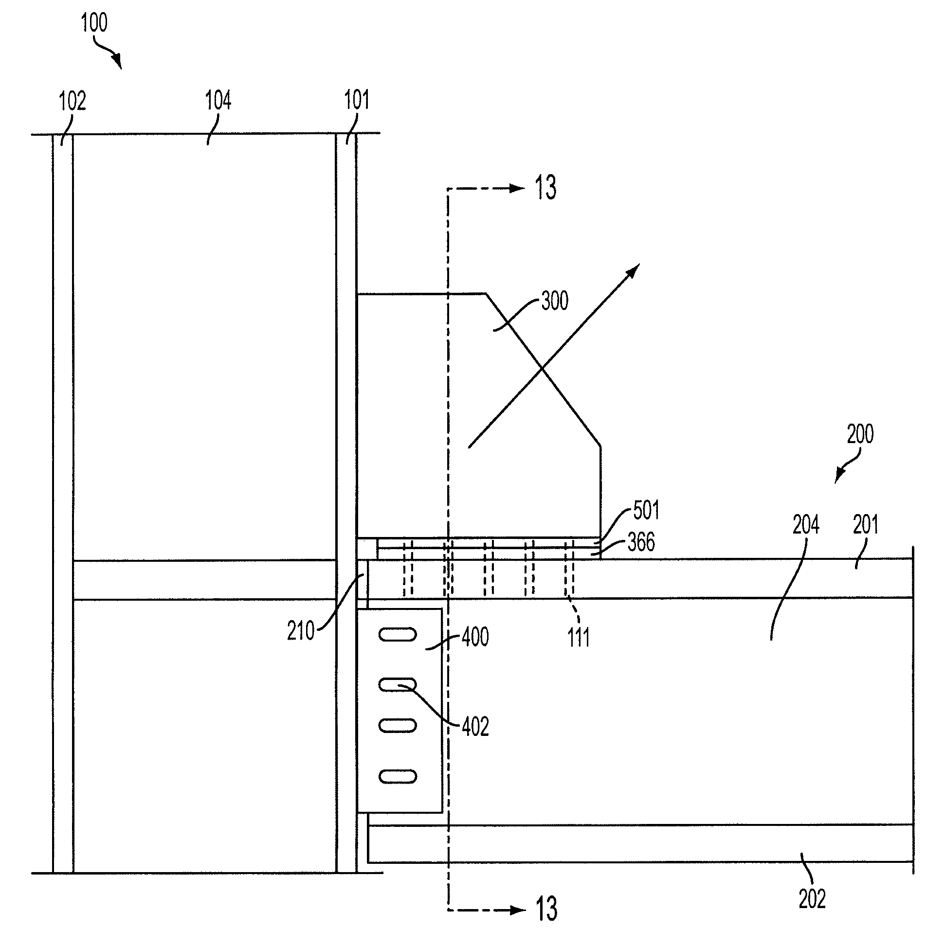
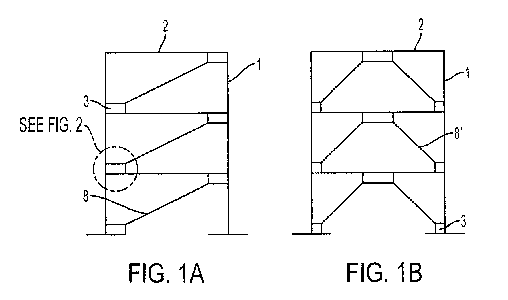
[0025]An embodiment of the present invention provides a new and improved beam-to-column-to-brace connection, which includes a gusset plate, that reduces the bending moments and shears in the beams and columns of conventionally joined braced frames when the structural framework may be subjected to gravity and lateral loads such as those caused by wind and seismic loadings. The improved connection may extend the useful life of new braced framed structures, as well as that of braced frames in existing structures when incorporated into a retrofit modification for existing structures

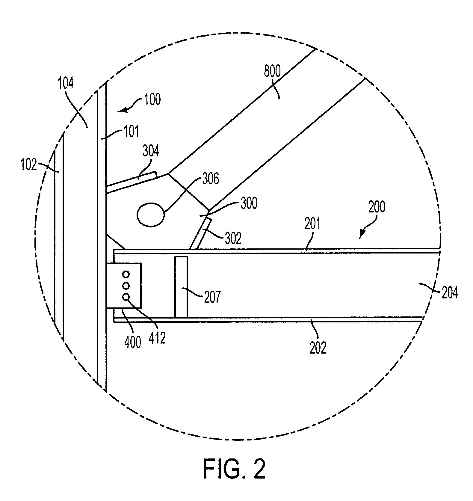
[0026]The moments and shears in the beams and columns may be reduced by two ways. First, a flexure mechanism may be provided to transfer the horizontal forces in the gusset plate to the beam. Second, a shear plate may be provided to bolt the beam web to the column flange connection such that the shear plate includes horizontally slotted holes.

[0027]The flexure mechanism may include either (1) a beam web slot ...


PUM


Abstract

A structural framework that includes a column, a beam, a brace beam coupled at an angle to the column and the beam, and a gusset plate to connect the brace beam with the column and the beam. The framework also includes a shear plate with horizontally slotted holes to couple to the column to the beam. The structural framework may also include double framing angles or a flex plate coupled to the gusset plate and to the beam via spacer plates to provide for a semi-rigid connection.

Description

CROSS-REFERENCE TO RELATED APPLICATION[0001]This application claims the benefit of provisional patent application No. 61 / 006,188, filed on Dec. 28, 2007, which is incorporated herein by reference.FIELD OF THE INVENTION[0002]Embodiments of the present invention relate broadly to a method of construction and design of members of load bearing and braced frames and their connections to enhance and provide for high resistance and ductile behavior of the frames when subjected to loading such as gravity, seismic, and wind loading. More specifically, embodiments of the present invention relate to the design and construction of structural frame members and their connections that use gusset plates to join the beams and columns to the lateral load carrying frame brace members. Embodiments of the present invention may be used, but not necessarily exclusively used, in steel frame buildings, in new construction as well as modification of existing structures.BACKGROUND OF THE INVENTION[0003]In the...

Claims


Application Information

Patent Timeline
IPC IPC(8): E04H12/10E04H12/08
CPCE04B1/24E04B2001/2415E04B2001/2439E04B2001/2442E04H9/14E04B2001/2496E04H9/028E04H9/021E04B2001/2448E04H9/0237E04C3/02E04C3/09E04C5/0645E04C2003/0404
Inventor RICHARD, RALPH M.RADAU, JR., RUDOLPH E.PARTRIDGE, JAMES E.ALLEN, CLAYTON J.
Owner SEISMIC STRUCTURAL DESIGN ASSOCS
Why Eureka
Try Eureka