
Zoom lens and imaging apparatus

Inactive Publication Date: 2009-07-02
SONY CORP
View PDF1 Cites 13 Cited by
  • Summary
  • Abstract
  • Description
  • Claims
  • Application Information

AI Technical Summary

Benefits of technology

[0006]However, in the zoom lens in the shake-correcting optical system described in Patent Document 1, the negative part group of the fifth lens group is made up of one negative lens, and thus, the refractive power of the negative part group is strong, which makes large a refractive power difference from a lens closest to the image of the positive part group of the fifth lens group. Accordingly, there has been an issue of increased deterioration in image formation performance, which is caused by relative decentering between the negative part group of the fifth lens group and the lens closest to the image of the positive part group of the fifth lens group.

Problems solved by technology

Accordingly, there has been an issue of increased deterioration in image formation performance, which is caused by relative decentering between the negative part group of the fifth lens group and the lens closest to the image of the positive part group of the fifth lens group.
However, this has an issue that corresponding to this movement amount of the second lens group, there also arises need to increase a movement amount of the fourth lens group, which makes fluctuations in aberration large with this, and thus, makes the correction of aberration in the entire zoom area difficult, so that it is difficult to achieve higher performance and higher variable power.

Method used


Image

  • Zoom lens and imaging apparatus
  • Zoom lens and imaging apparatus
  • Zoom lens and imaging apparatus

Examples


first embodiment

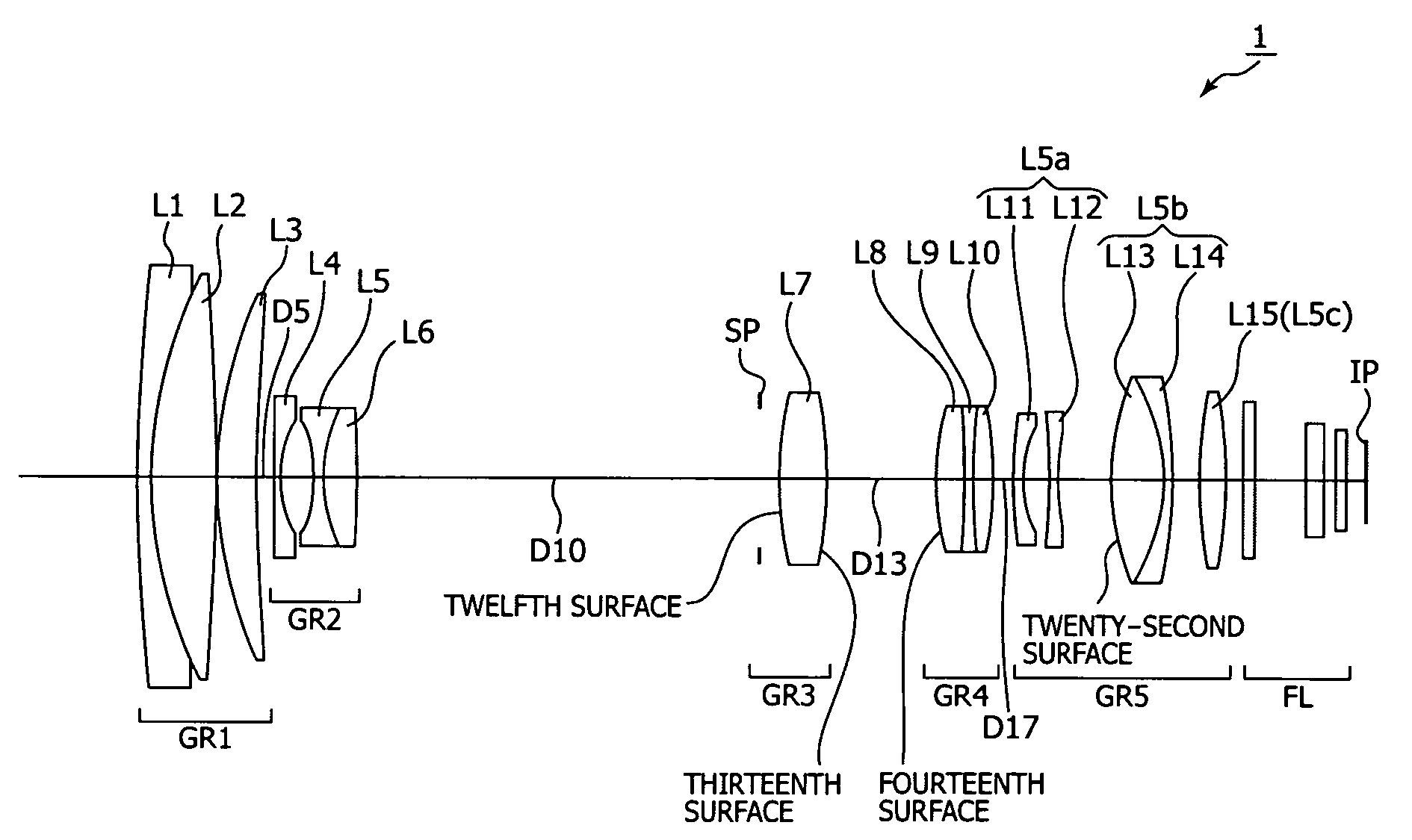
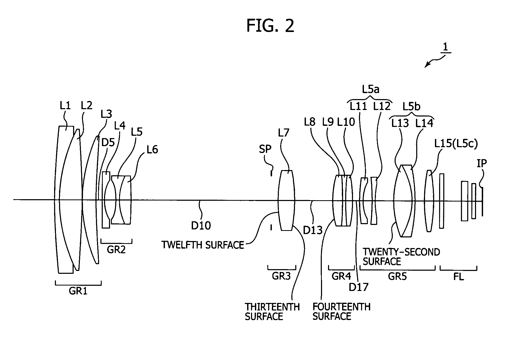
[0093]FIG. 2 is a diagram showing a lens configuration of a zoom lens 1 according to the present invention.

[0094]In the first lens group GR1, a negative lens (first lens) L1 having a concave meniscus shape with a convex surface facing the object side, a positive lens (second lens) L2 which is a convex lens cemented to the negative lens L1, and a positive lens (third lens) L3 having a convex meniscus shape with a convex surface facing the object side are located in order from the object side to the image side.

[0095]In the second lens group GR2, a negative lens (fourth lens) L4 having a concave meniscus shape with a convex surface facing the object side, a biconcave lens (fifth lens) L5, and a biconvex lens (sixth lens) L6 cemented to the biconcave lens L5 are located in order from the object side to the image side.

[0096]The third lens group GR3 is made up of a biconvex lens (seventh lens) L7 having aspherical surfaces on both surfaces thereof.

[0097]In the fourth lens group GR4, three...

second embodiment

[0112]FIG. 9 is a diagram showing a lens configuration of a zoom lens 2 according to the present invention.

[0113]In the first lens group GR1, the negative lens (first lens) L1 having a concave meniscus shape with a convex surface facing the object side, the positive lens (second lens) L2 which is a convex lens cemented to the negative lens L1, and the positive lens (third lens) L3 having a convex meniscus shape with a convex surface facing the object side are located in order from the object side to the image side.

[0114]In the second lens group GR2, the negative lens (fourth lens) L4 having a concave meniscus shape with a convex surface facing the object side, the biconcave lens (fifth lens) L5, and the biconvex lens (sixth lens) L6 cemented to the biconcave lens L5 are located in order from the object side to the image side.

[0115]The third lens group GR3 is made up of the biconvex lens (seventh lens) L7 having aspherical surfaces on both surfaces thereof.

[0116]In the fourth lens gr...

third embodiment

[0129]FIG. 16 is a diagram showing a lens configuration of a zoom lens 3 according to the present invention.

[0130]In the first lens group GR1, the negative lens (first lens) L1 having a concave meniscus shape with a convex surface facing the object side, the positive lens (second lens) L2 which is a convex lens cemented to the negative lens L1, and the positive lens (third lens) L3 having a convex meniscus shape with a convex surface facing the object side are located in order from the object side to the image side.

[0131]In the second lens group GR2, the negative lens (fourth lens) L4 having a concave meniscus shape with a convex surface facing the object side, the biconcave lens (fifth lens) L5, and the biconvex lens (sixth lens) L6 cemented to the biconcave lens L5 are located in order from the object side to the image side.

[0132]The third lens group GR3 is made up of the biconvex lens (seventh lens) L7 having aspherical surfaces on both surfaces thereof.

[0133]In the fourth lens g...


PUM


Abstract

A zoom lens configured by arranging a first lens group, a second lens group, a third lens group, a fourth lens group, and a fifth lens group in order from the object side to the image side, and further having an aperture diaphragm on the object side of the third lens group. In the first lens group, a first lens, a second lens, and a third lens are located in order from the object side to the image side. In the second lens group, a fourth lens, a fifth lens, and a sixth lens are located in order from the object side to the image side. The third lens group is made up of a seventh lens which is a convex lens, the fourth lens group is made up of at least two or more cemented lenses, the third lens group and the fourth lens group include at least one surface formed into an aspherical surface.

Description

BACKGROUND OF THE INVENTION[0001]1. Field of the Invention[0002]The present invention relates to a zoom lens and an imaging apparatus. More particularly, the present invention relates to an a zoom lens and an imaging apparatus having a so-called vibration-proof function in which a blur of a photographed image is optically corrected when vibrated to obtain an image free from a blur by moving a part of lens groups so as to have a component in a direction perpendicular to an optical axis, thereby resulting in stabilization of the photographed image, and further having a higher variable power ratio of about 15 to 20 times.[0003]2. Description of Related Art[0004]During photographing of an imaging apparatus, such as a still camera, a video camera and the like, for example, the occurrence of camera shake attributed to shutter operation or shake caused by transmitting vibration to a photographing system when a subject is photographed from a moving object such as a car results in a blur on ...

Claims


Application Information

Patent Timeline
IPC IPC(8): G02B15/16
CPCG02B27/646G02B15/173G02B15/145129
Inventor SUZAKI, MITSUHIRONANJO, YUSUKEARITA, SHINICHI
Owner SONY CORP
Learn More