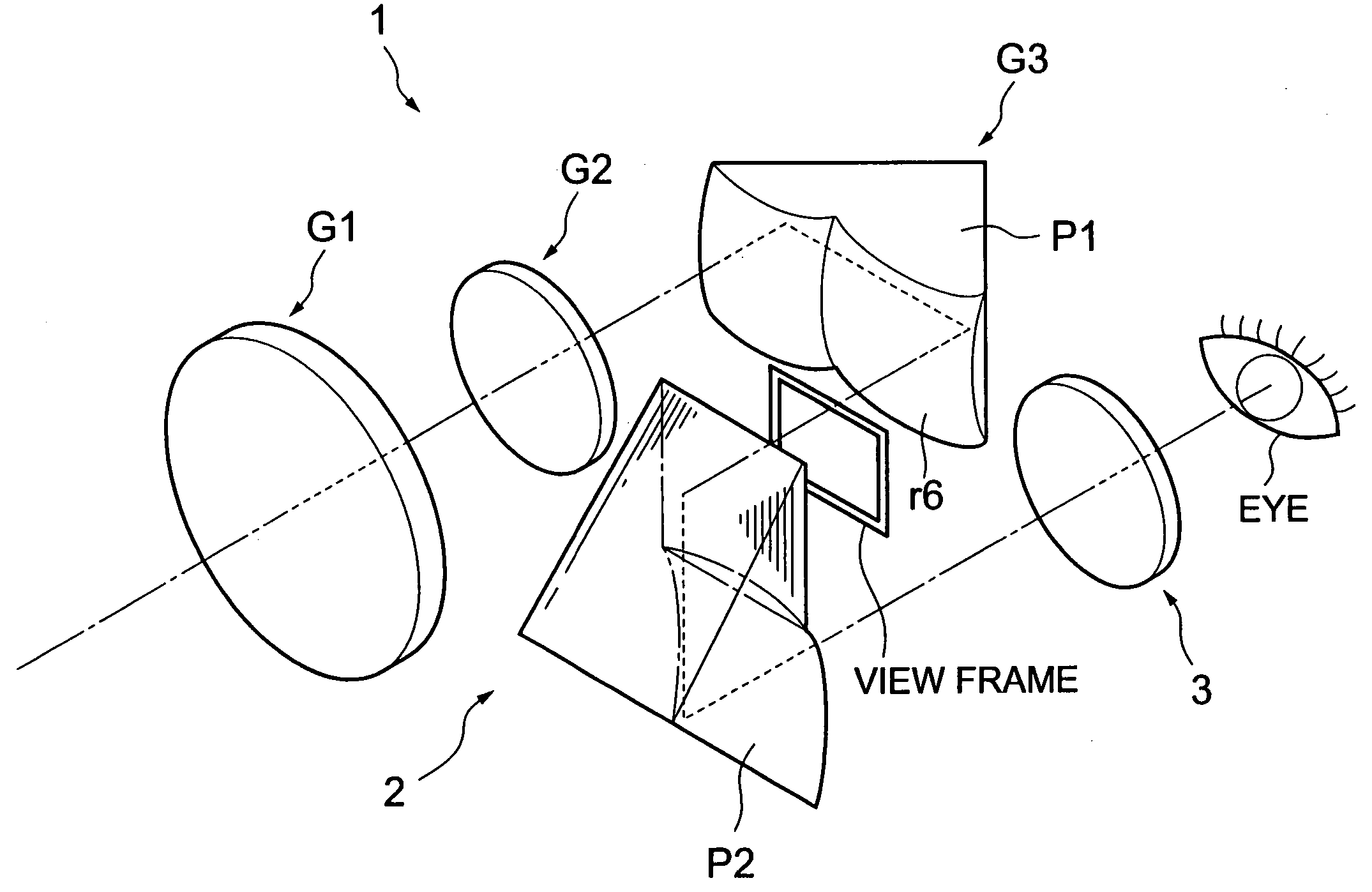
Variable power finder and imaging apparatus
a technology imaging apparatus, which is applied in the field of variable power finder, can solve the problems of difficult to excellently compensate the various aberrations, and achieve the effects of good optical performance, excellent mass production, and small siz
- Summary
- Abstract
- Description
- Claims
- Application Information
AI Technical Summary
Benefits of technology
Problems solved by technology
Method used
Image
Examples
example 1
Examples 1 to 4 below will be described referring to the values according to the present invention. In the respective examples, the meanings of the symbols are as follows. 2ω: entire image angle of view in diagonal Si: the i-th surface counted from object side Ri: curvature radius of the above i-th surface Si di: distance between the i-th surface and the (i+1)-th surface from object side ni: refractive index in d-line (wavelength 587.6 nm) of the i-th lens νi: the Abbe' number of the i-th lens *: surface where aspherical surface is used
Also, the aspherical shape is defined by the following equation 1, where the depth of the aspherical surface is assumed to be X, and the height from the optical axis is assumed to be H. In the equation 1, A, B, C, and D are the fourth, sixth, eighth and tenth aspherical coefficients, respectively. X=H2R1+1-(HR)2+AH4+BH6+CH8+DH10Equation 1
FIG. 3A to 3C are optical system configuration views of a variable power finder according to Example 1....
example 2
FIG. 7A to 7C are optical system configuration views of a variable power finder according to Example 2. FIG. 8A to 8C are aberration views corresponding to the wide angle end (WIDE) of the variable power finder according to Example 2. FIG. 9A to 9C are aberration views corresponding to the middle (MID) of the variable power finder according to Example 2. And, FIG. 10A to 10C are aberration views corresponding to the telescopic end (TELE) of the variable power finder according to Example 2.
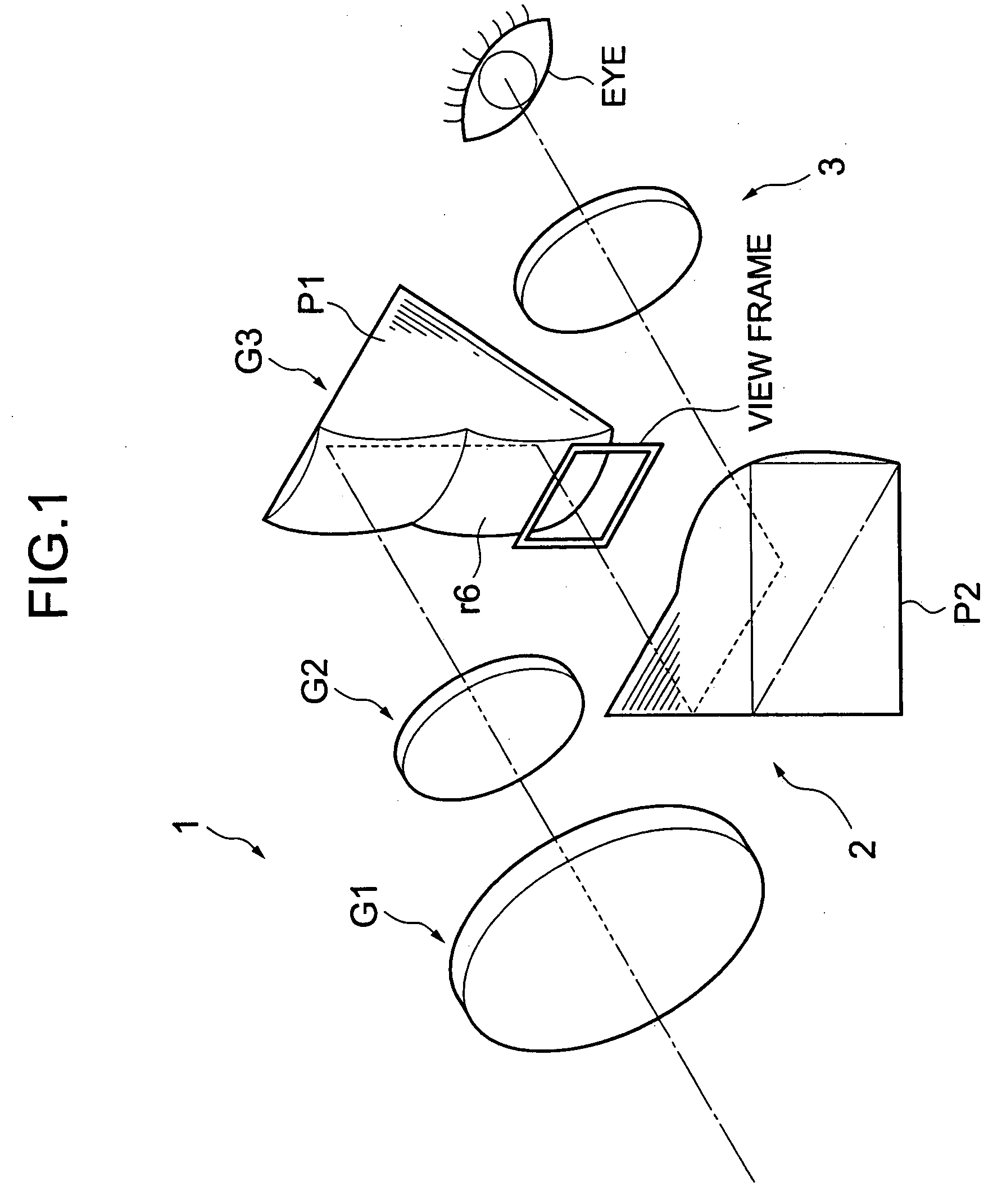
Here in Example 2, the configuration of the variable power finder is arranged according to the first embodiment of the arrangement shown in FIG. 1.
Also, Table 5 is the data indicating the configuration of the optical system according to Example 2. Table 6 is the data indicating the aspherical coefficients according to Example 2. Table 7 is the data indicating the change in the distance between the groups caused by the variable power according to Example 2. And, Table 8 is the data indicating of...
example 3
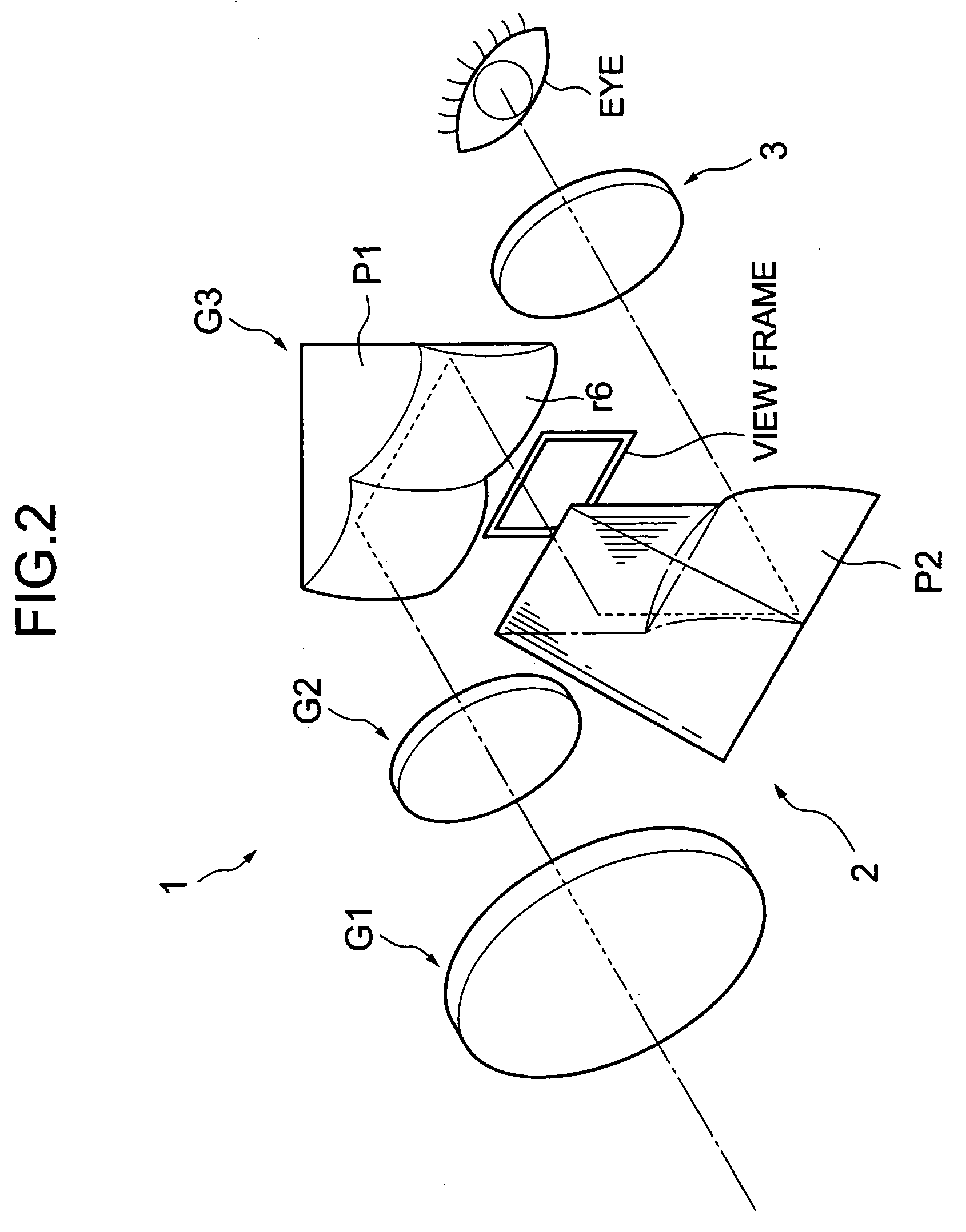
FIG. 11A to 11C are optical system configuration views of a variable power finder according to Example 3. FIG. 12A to 12C are aberration views corresponding to the wide angle end (WIDE) of the variable power finder according to Example 3. FIG. 13A to 13C are aberration views corresponding to the middle (MID) of the variable power finder according to Example 3. And, FIG. 14A to 14C are aberration views corresponding to the telescopic end (TELE) of the variable power according to Example 3. Here in Example 3, the configuration of the variable power finder is arranged according to the second embodiment of the arrangement shown in FIG. 2.
Also, Table 9 is the data indicating the configuration of the optical system according to Example 3. Table 10 is the data indicating the aspherical coefficients according to Example 3. Table 11 is the data indicating the change in distance between the groups caused by the variable power according to Example 3. And, Table 12 is the data indicating the ...
PUM
 Abstract
Description
Claims
Application Information
 - R&D
- Intellectual Property
- Life Sciences
- Materials
- Tech Scout
- Unparalleled Data Quality
- Higher Quality Content
- 60% Fewer Hallucinations
Browse by: Latest US Patents, China's latest patents, Technical Efficacy Thesaurus, Application Domain, Technology Topic, Popular Technical Reports.
© 2025 PatSnap. All rights reserved.Legal|Privacy policy|Modern Slavery Act Transparency Statement|Sitemap|About US| Contact US: help@patsnap.com


