Variable focal length lens system and imaging apparatus
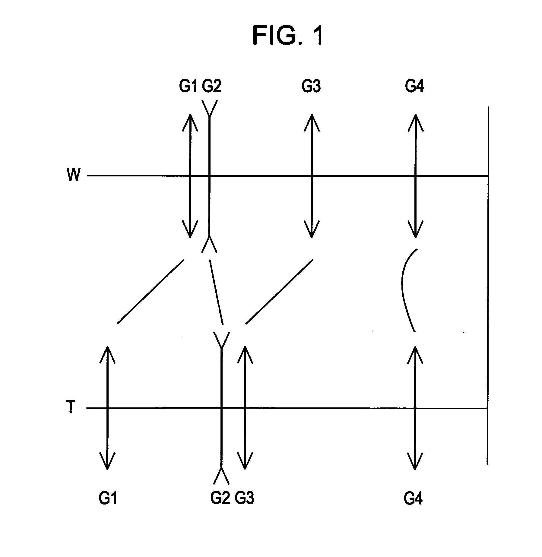
a lens system and variable technology, applied in the field of variable focal length lens system and imaging apparatus, can solve the problems of difficult to sufficiently reduce the overall length or diameter of the lens, the diameter of the first lens group increases, and the performance is likely to deteriorate significantly, so as to reduce the thickness of the lens, improve the effect of variable power and small siz
- Summary
- Abstract
- Description
- Claims
- Application Information
AI Technical Summary
Benefits of technology
Problems solved by technology
Method used
Image
Examples
numerical examples
[0184]Next, exemplary embodiments of the variable focal length lens system according to the invention and numerical examples in which detailed numerical values are applied to the embodiments will be described with reference to the drawings and tables.
[0185]The meaning of the symbols in the following tables or description is as follows.
[0186]“f” indicates a focal length, “Fno” indicates the F number, “2ω” indicates an angle of view, “Di” indicates the surface spacing between an i-th surface and an (i+1)-th surface on the axis. Surface number “S” indicates an aperture diaphragm, and curvature radius “ASP” indicates an aspheric surface. “K” indicates a conic constant, “A”, “B”, “C”, and “D” indicate 4th-order, 6th-order, 8th-order, and 10th-order aspheric coefficients, respectively, and “Bf” indicates a back focal length.
[0187]The refractive index is a value with respect to the d-line (λ=587.6 nm), and a curvature radius of “0.0000” indicates that the surface is flat.
[0188]The lenses u...
first embodiment
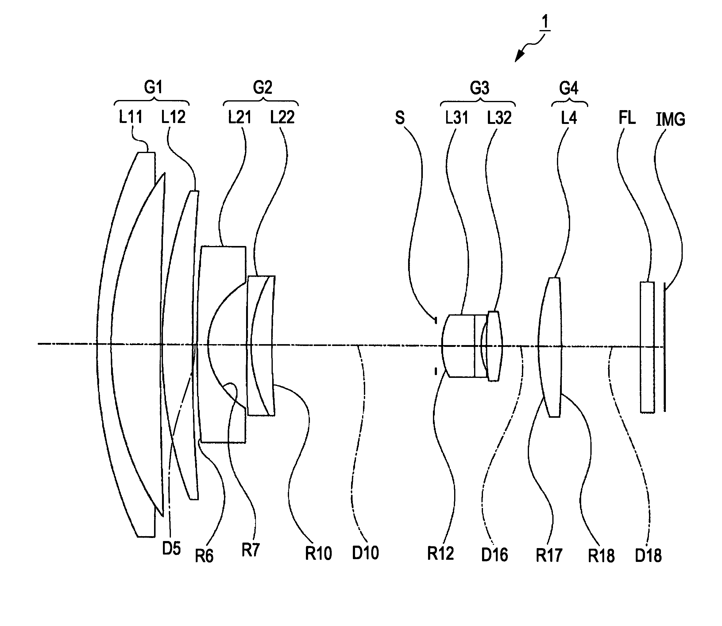
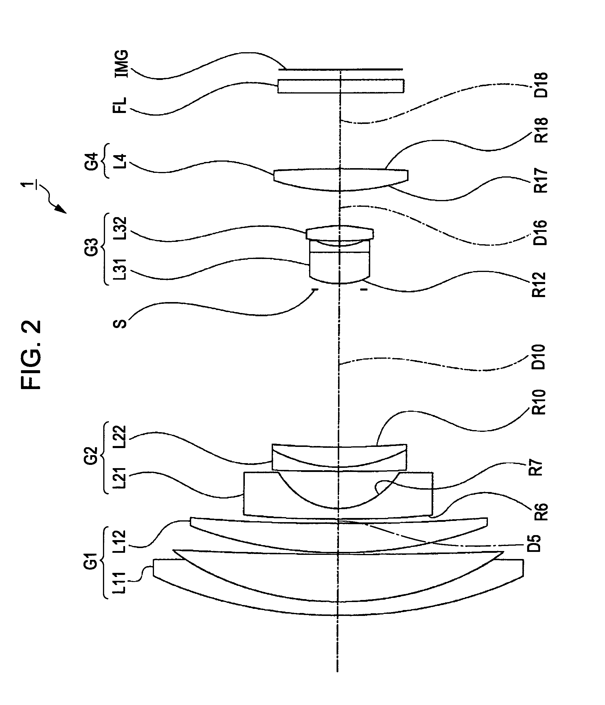
[0192]FIG. 2 is a diagram illustrating the lens structure of a variable focal length lens system 1 according to a first embodiment of the invention. The variable focal length lens system 1 includes 10 lenses.
[0193]A first lens group G1 includes a cemented lens L11 of a meniscus-shaped negative lens having a convex surface facing the object side and a first positive lens having a convex surface facing the object side and a meniscus-shaped second positive lens L12 having a convex surface facing the object side.
[0194]A second lens group G2 includes a meniscus-shaped first negative lens L21 having a concave surface facing the image side and a cemented lens L22 of a second negative lens having a concave surface facing the image side and a positive lens having a convex surface facing the object side.
[0195]A third lens group G3 includes a cemented lens L31 of a first positive lens having a convex surface facing the object side and a negative lens having a concave surface facing the image s...
second embodiment
[0205]FIG. 6 is a diagram illustrating the lens structure of a variable focal length lens system 2 according to a second embodiment of the invention. The variable focal length lens system 2 includes 11 lenses.
[0206]A first lens group G1 includes a cemented lens L11 of a meniscus-shaped negative lens having a convex surface facing the object side and a first positive lens having a convex surface facing the object side and a meniscus-shaped second positive lens L12 having a convex surface facing the object side.
[0207]A second lens group G2 includes a meniscus-shaped first negative lens L21 having a concave surface facing the image side and a cemented lens L22 of a second negative lens having a concave surface facing the image side and a positive lens having a convex surface facing the object side.
[0208]A third lens group G3 includes a cemented lens L31 of a first positive lens having a convex surface facing the object side and a first negative lens having a concave surface facing the ...
PUM
 Abstract
Description
Claims
Application Information
 - R&D
- Intellectual Property
- Life Sciences
- Materials
- Tech Scout
- Unparalleled Data Quality
- Higher Quality Content
- 60% Fewer Hallucinations
Browse by: Latest US Patents, China's latest patents, Technical Efficacy Thesaurus, Application Domain, Technology Topic, Popular Technical Reports.
© 2025 PatSnap. All rights reserved.Legal|Privacy policy|Modern Slavery Act Transparency Statement|Sitemap|About US| Contact US: help@patsnap.com


