Zoom lens and optical apparatus equipped with this zoom lens
a zoom lens and optical apparatus technology, applied in the field of zoom lenses, can solve the problems of insufficient telephoto focal length, small variable power ratio, insufficient optical performance, etc., and achieve the effect of high variable power and high performan
- Summary
- Abstract
- Description
- Claims
- Application Information
AI Technical Summary
Benefits of technology
Problems solved by technology
Method used
Image
Examples
example 1
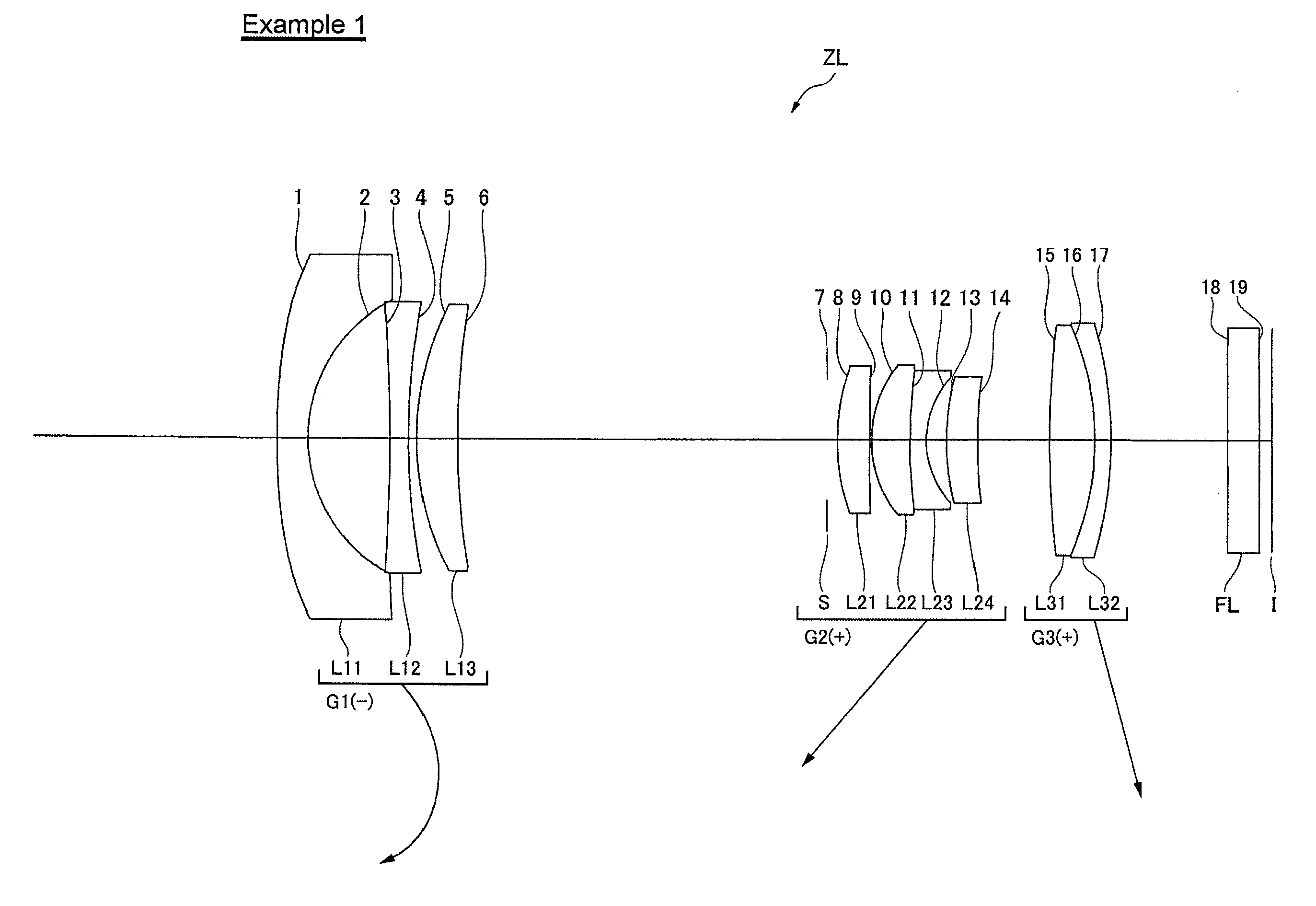
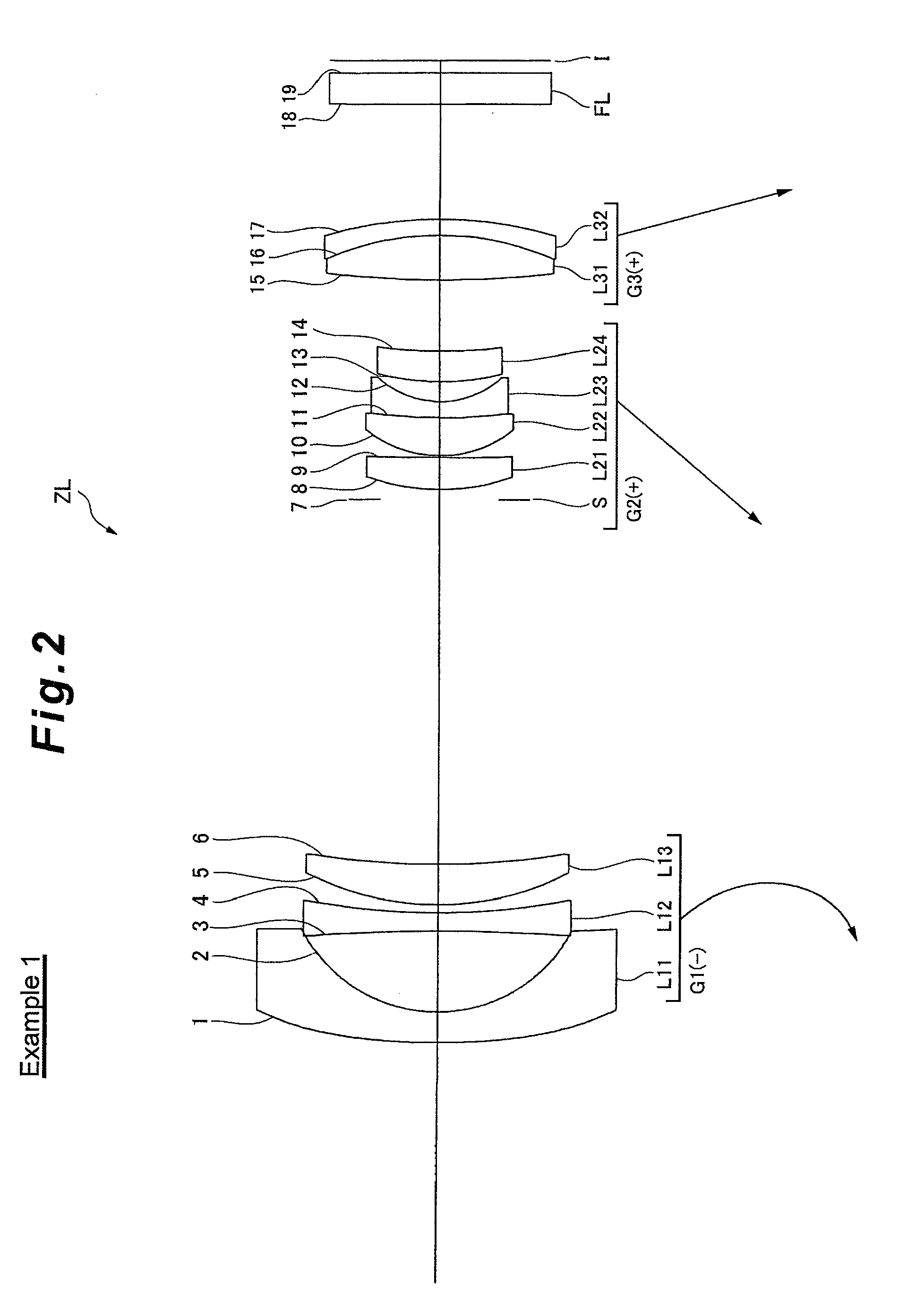
[0057]Example 1 will be described with reference to FIG. 2, FIG. 3 and Table 1. FIG. 2 shows the lens configuration and the zooming locus of Example 1. As FIG. 2 shows, in the zoom lens ZL according to this example, a first lens group G1 is comprised of a negative meniscus lens L11 having a concave surface facing the image, a biconcave negative lens L12, and a positive meniscus lens L13 having a convex surface facing the object, which are disposed in order from the object, and the lens surfaces facing the object and the image of the negative meniscus lens L11 are aspherical. A second lens group G2 is comprised of a positive meniscus lens L21 (first positive lens) having a convex surface facing the object, a cemented lens of a positive meniscus lens L22 having a convex surface facing the object and a negative meniscus lens 123 having a concave surface facing the image, and a positive meniscus lens L24 (second positive lens) having a convex surface facing the object, which are dispose...
example 2
[0065]Example 2 will be described with reference to FIG. 4, FIG. 5 and Table 2. FIG. 4 shows the lens configuration and the zooming locus of Example 2. As FIG. 4 shows, in the zoom lens ZL according to this example, a first lens group G1 is comprised of a negative meniscus lens L11 having a concave surface facing the image, a biconcave negative lens L12, and a positive meniscus lens L13 having a convex surface facing the object, which are disposed in order from the object, and the lens surfaces facing the object and the image of the negative meniscus lens L11 are aspherical. A second lens group G2 is comprised of a positive meniscus lens L21 (first positive lens) having a convex surface facing the object, a cemented lens of a positive meniscus lens L22 having a convex surface facing the object and a negative meniscus lens L23 having a concave surface facing the image, and a positive meniscus lens L24 (second positive lens) having a convex surface facing the object, which are dispose...
example 3
[0072]Example 3 will be described with reference to FIG. 6, FIG. 7 and Table 3. FIG. 6 shows the lens configuration and the zooming locus of Example 3. As FIG. 6 shows, in the zoom lens ZL according to this example, a first lens group G1 is comprised of a negative meniscus lens L11 having a concave surface facing the image, a biconcave negative lens L12, and a positive meniscus lens L13 having a convex surface facing the object, which are disposed in order from the object, and the lens surfaces facing the object and the image of the negative meniscus lens L11 are aspherical. A second lens group G2 is comprised of a positive meniscus lens L21 (first positive lens) having a convex surface facing the object, a cemented lens of a biconvex positive lens L22 having a convex surface facing the object and a biconcave negative lens L23 having a concave surface facing the image, and a biconvex positive lens L24 (second positive lens) having a convex surface facing the object, which are dispos...
PUM
 Abstract
Description
Claims
Application Information
 - R&D
- Intellectual Property
- Life Sciences
- Materials
- Tech Scout
- Unparalleled Data Quality
- Higher Quality Content
- 60% Fewer Hallucinations
Browse by: Latest US Patents, China's latest patents, Technical Efficacy Thesaurus, Application Domain, Technology Topic, Popular Technical Reports.
© 2025 PatSnap. All rights reserved.Legal|Privacy policy|Modern Slavery Act Transparency Statement|Sitemap|About US| Contact US: help@patsnap.com


