
Magnetostrictive measurement of tensile stress in foundations

a tensile stress and magnetic force technology, applied in the field of foundations, can solve the problems of large amount of reinforcing, upset forces may also be applied at the foundation, and the foundation can be subject to very high compressive and tensile forces

Active Publication Date: 2009-07-02
GENERAL ELECTRIC CO
View PDF15 Cites 18 Cited by
  • Summary
  • Abstract
  • Description
  • Claims
  • Application Information

AI Technical Summary

Problems solved by technology

Large foundations often require a large amount of reinforcing steel and a large amount of concrete to encase the reinforcing steel.
Such foundations can be subject to very high compressive and tensile forces.
Thereby, upset forces may also be applied at the foundation.
In light of friction and other manufacturing aspects this method might not provide the desired accuracy.
Load measurements are difficult to perform, in particular since many of the structural components cannot be accessed as they are embedded in concrete or the like.
However, these methods can only be performed off-line.

Method used


Image

  • Magnetostrictive measurement of tensile stress in foundations
  • Magnetostrictive measurement of tensile stress in foundations
  • Magnetostrictive measurement of tensile stress in foundations

Examples


Embodiment Construction

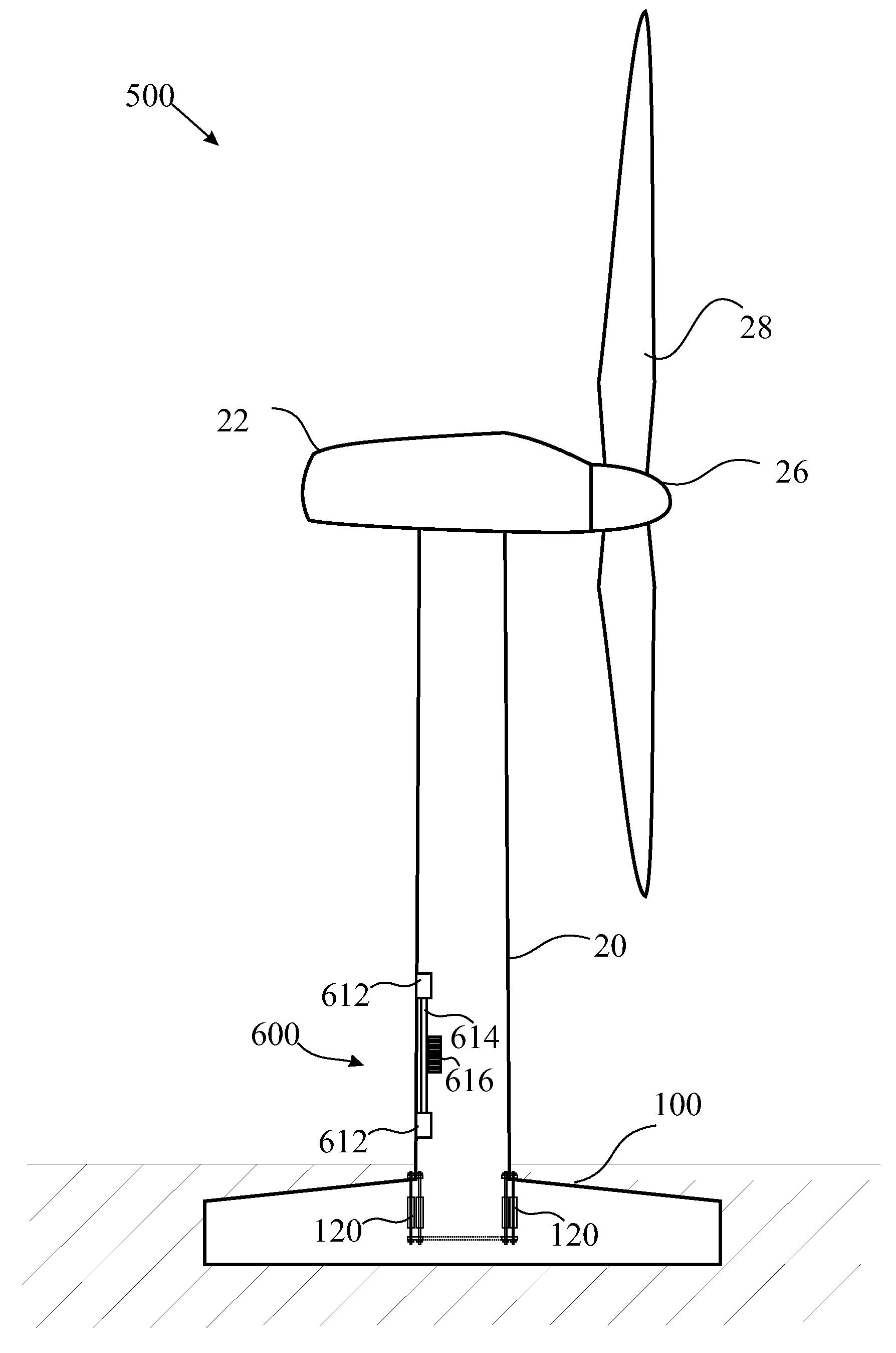
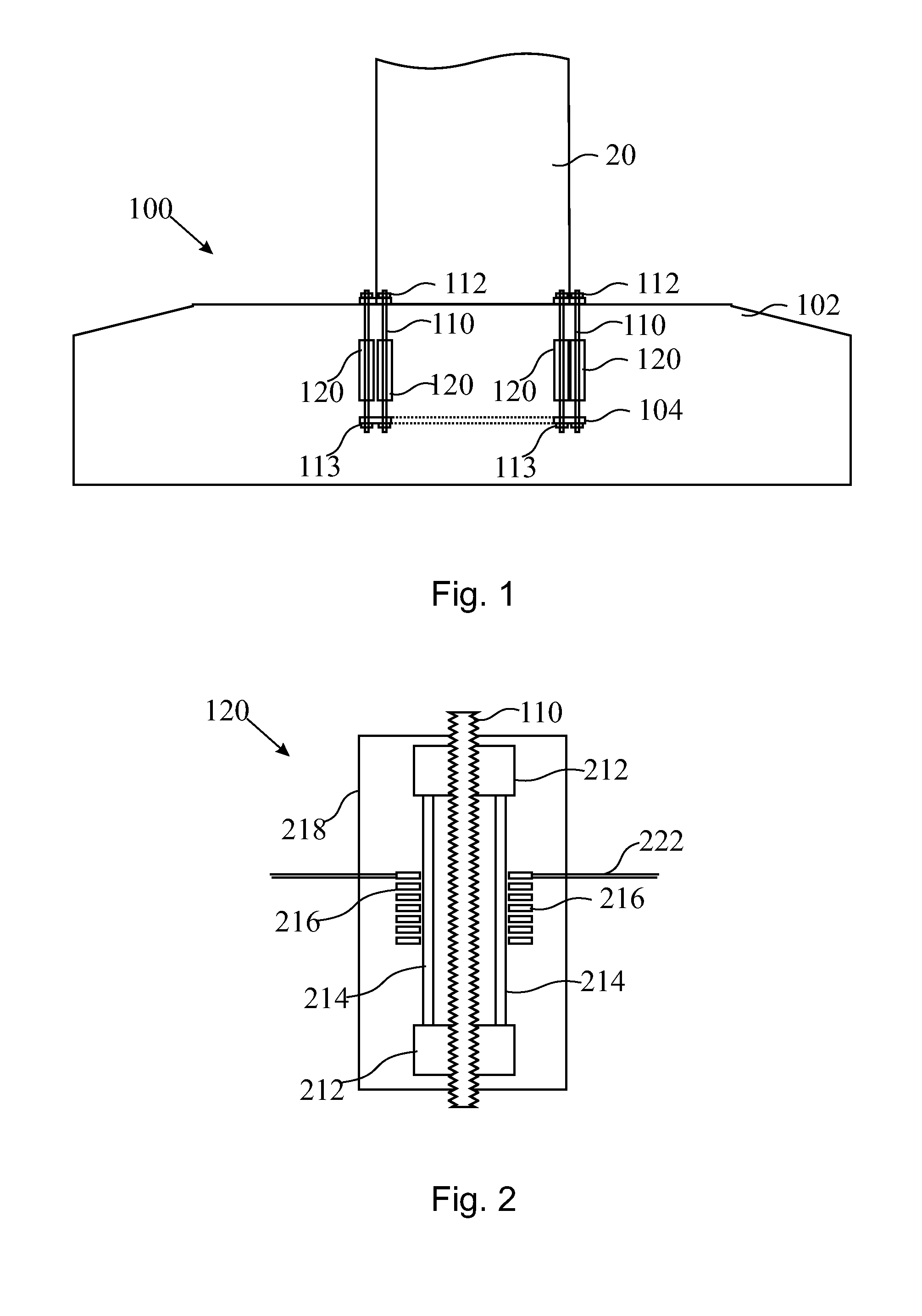
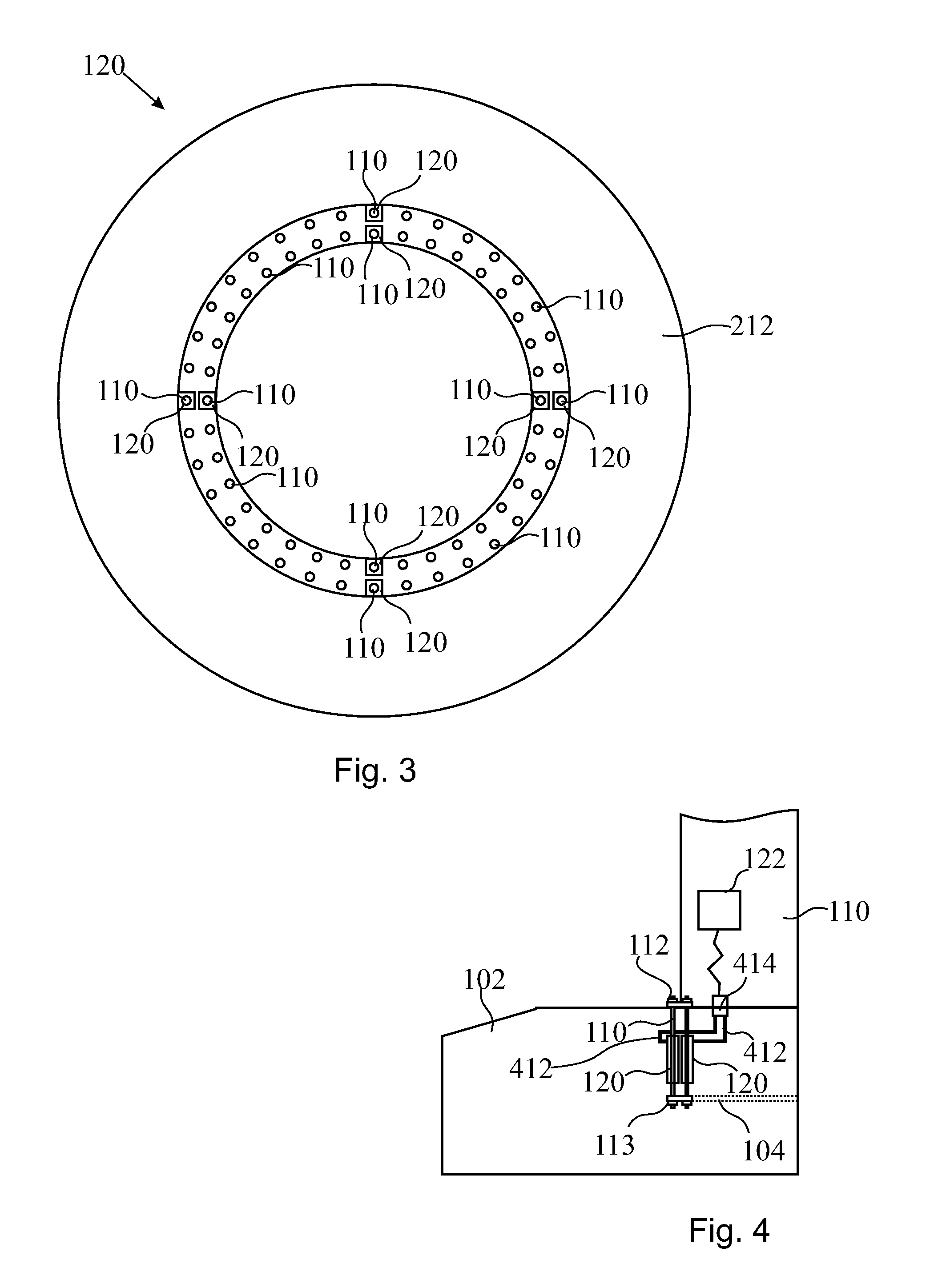
[0018]Reference will now be made in detail to the various embodiments of the invention, one or more examples of which are illustrated in the figures. Each example is provided by way of explanation of the invention, and is not meant as a limitation of the invention. For example, features illustrated or described as part of one embodiment can be used on or in conjunction with other embodiments to yield yet a further embodiment. It is intended that the present invention includes such modifications and variations.

[0019]Generally, within concrete pier foundations the concrete bears compressive loads. Tensile loads can be borne by reinforcement bars contained in the foundation. Anchor bolts are typically used for attaching the supported structure to the foundation. The anchor bolts can be placed within the reinforcing steel matrix or a reinforcing steel cage. Thereby, it is for example possible to use a removable template at the top and a separate anchor plate at the bottom of each bolt i...


PUM

PropertyMeasurementUnit
distanceaaaaaaaaaa
distanceaaaaaaaaaa
distanceaaaaaaaaaa

Abstract

A foundation for supporting a structure is provided. The foundation includes a foundation body, at least one anchor bolt connecting a lower anchor plate and the structure, a magnetostrictive load measuring sensor for measuring loads on the at least one anchor bolt, the magnetostrictive load measuring sensor being positioned within the foundation body.

Description

BACKGROUND OF THE INVENTION[0001]The present invention relates to foundations and, in particular, reinforced concrete foundations like concrete pier foundations for support of tall, heavy or large structures like towers. Further, the present invention relates methods of measuring tensile stress in a foundation. More particularly, it relates to foundations for a wind turbine and a method for measuring tensile stress in a foundation component. Specifically, it relates to a foundation for supporting a structure, a wind turbine and a method for measuring tensile stress in a foundation.[0002]To optimize foundations for structures, e.g. towers and the like, which may be used to support power lines, communication systems, street lighting and street signals, bridge supports, commercial science, freeway signs, ski lifts, and wind turbines, a measurement of loads in the reinforcement bolts that are contained in the concrete foundation is desirable. Load measurements in the foundation can be u...

Claims


Application Information

Patent Timeline
Patent Type & Authority Applications(United States)
IPC IPC(8): F03D11/04E02D27/32G01L1/12F03D1/00
CPCE02D33/00G01L5/0004G01M5/0091G01M5/0041G01M5/00Y02E10/728Y02E10/72G01L1/12G01B7/16
Inventor NIES, JACOB JOHANNESHEMMELMANN, JAN ERICHSIHLER, CHRISTOF MARTIN
Owner GENERAL ELECTRIC CO
Learn More