
Flitch planer

a technology of flitch and planer, which is applied in the field of flitch planers, can solve the problems of no better art than, and achieve the effect of optimizing the yield of flitch

Inactive Publication Date: 2009-07-09
PADANA
View PDF11 Cites 1 Cited by
  • Summary
  • Abstract
  • Description
  • Claims
  • Application Information

AI Technical Summary

Problems solved by technology

No representation is intended by this listing that a thorough search of all material prior art has been conducted, or that no better art than that listed is available.

Method used


Image

  • Flitch planer
  • Flitch planer
  • Flitch planer

Examples


Embodiment Construction

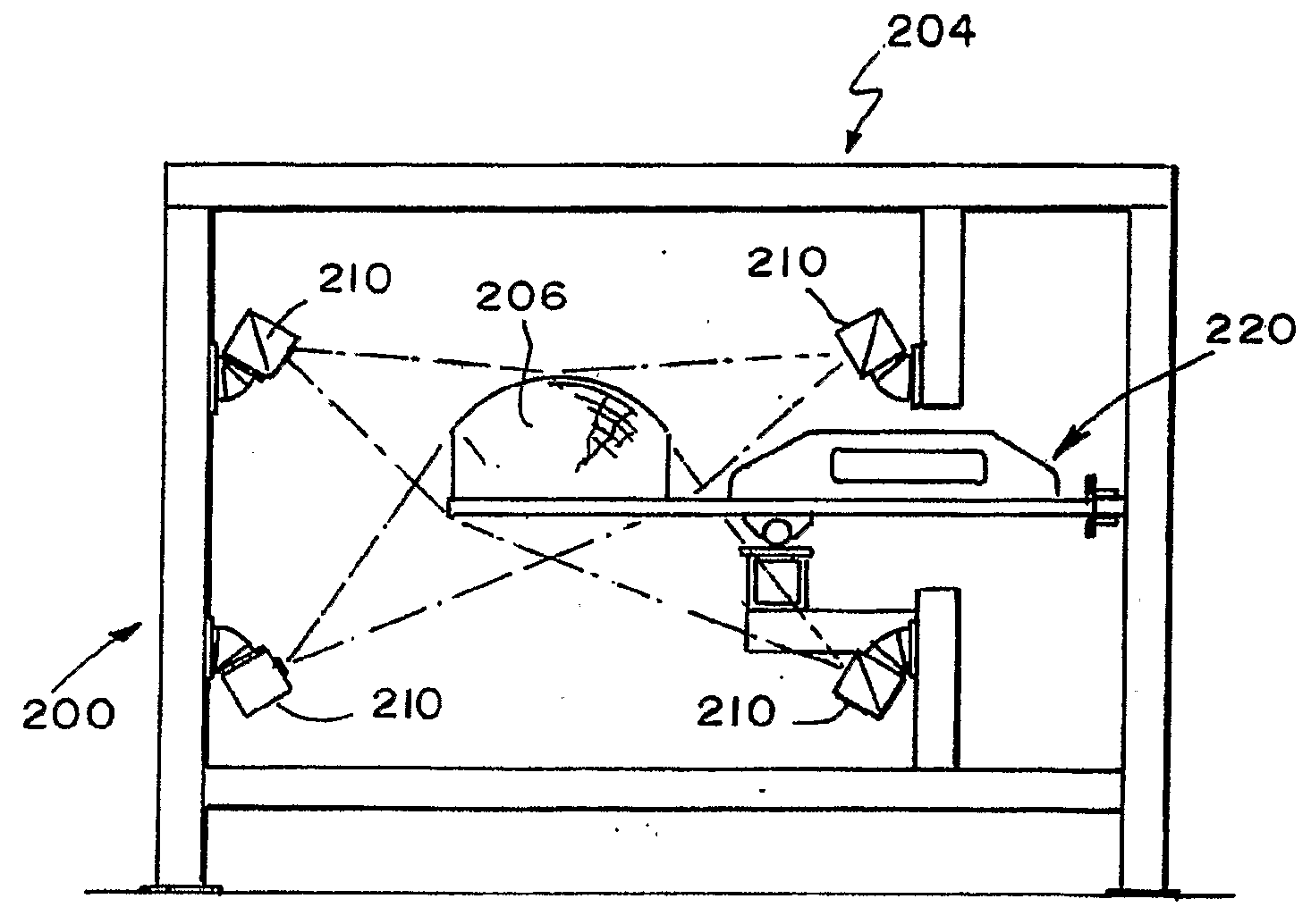
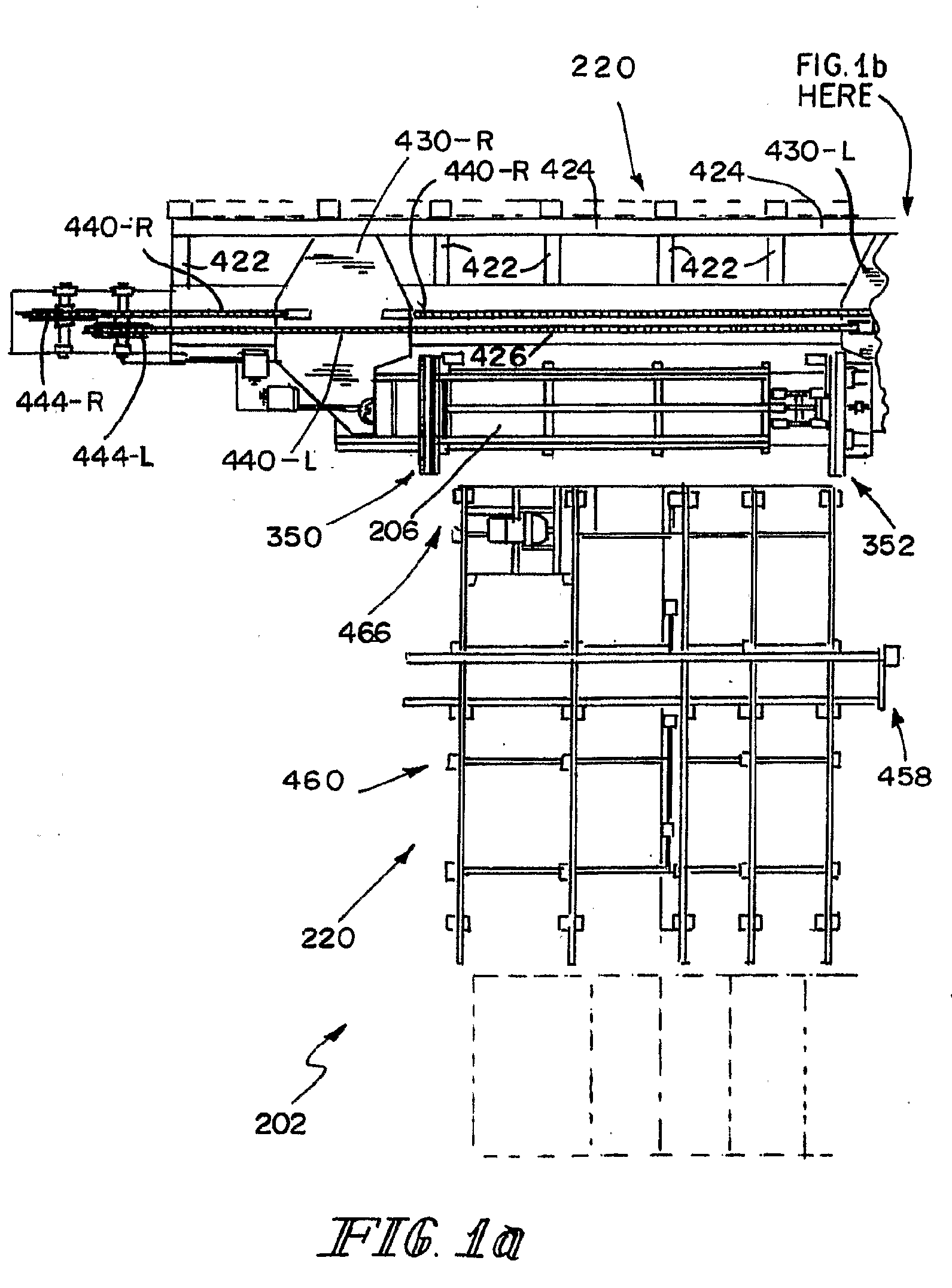
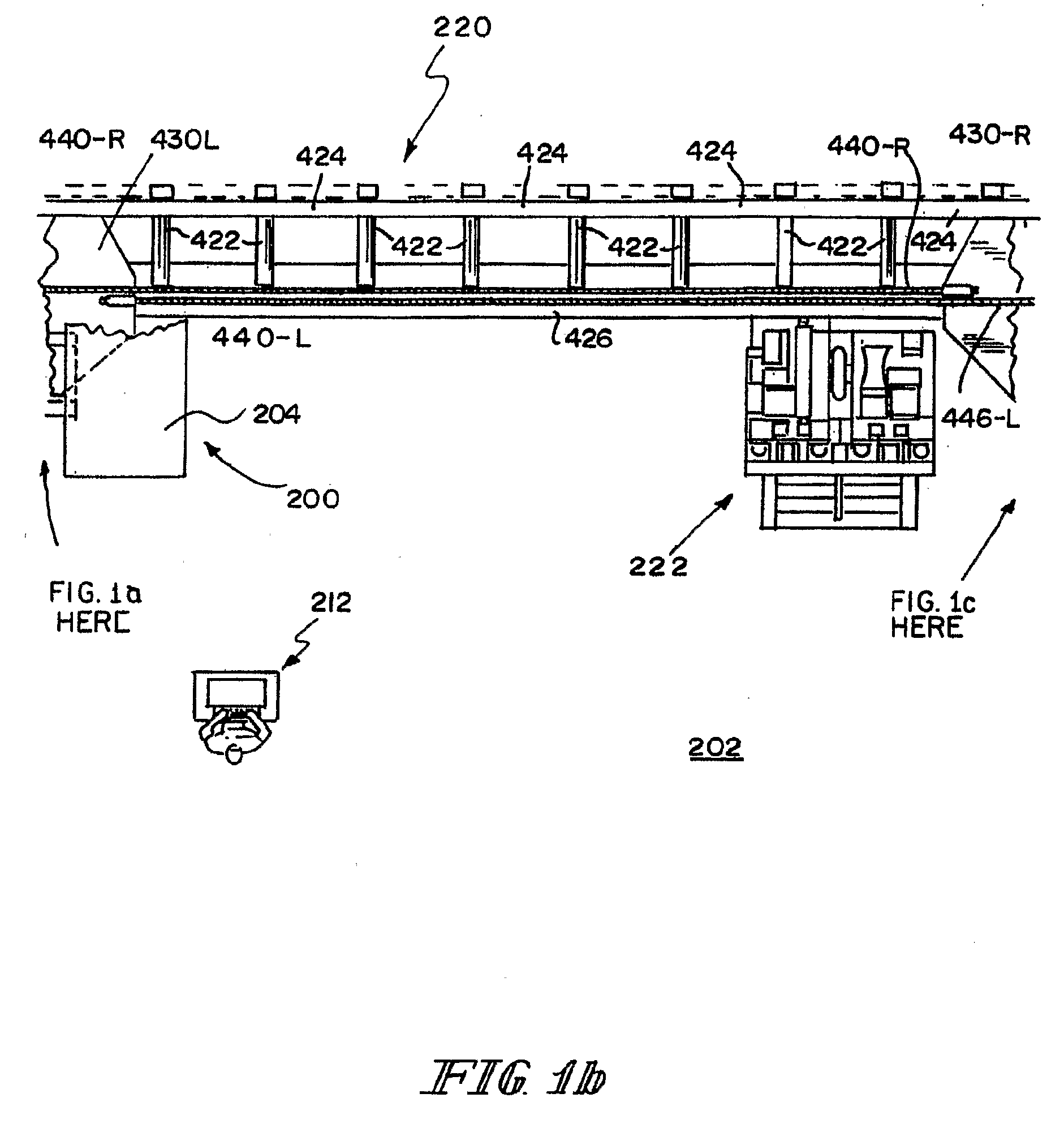
[0055]Referring first to FIGS. 1a-c, a top plan view of a system incorporating a flitch planer 202 according to the invention, a scanner section 200 includes an enclosure 204 (see also FIGS. 2a-d) through which a flitch 206 to be planed, or shaped, passes for scanning by a number, illustratively, four, of scanners 210, for example, model DiSCAN 100 optical scanners available from Microtec S. r. 1. / GmbH, Brixen, Italy, as part of a DiSHAPE 100 / 4 3D shape scanner. See FIG. 3. The outputs of the scanners 210 are coupled by appropriate conductors (not shown) to a control system 212 including, for example, an appropriately programmed personal computer (hereinafter sometimes PC), the program of which calculates an optimum shaping strategy for the flitch 206 being scanned. A conveyor 220 extends through enclosure 204 and conveys the flitch 206 through the enclosure 204 past the scanners 210, where the flitch 206 is scanned and parameters obtained from the scanning are output to the control...


PUM


Abstract

Apparatus for shaping a flitch includes an upper shaping head assembly for shaping an upper surface of the flitch, a lower shaping head assembly for shaping a lower surface of the flitch, and a groover assembly for placing at least one groove in a surface of the flitch. The apparatus further includes at least one centering arm and chain runner assembly. The at least one centering arm and chain runner assembly includes a chain runner assembly for conveying the flitch toward a transverse center of the centering arm and chain runner assembly, and a centering arm assembly for positioning the flitch. A flitch transport conveyor includes a conveyor frame, a first dogger arm assembly for engaging a first end of the flitch, and a second dogger arm assembly for engaging a second end of the flitch.

Description

CROSS-REFERENCE TO RELATED APPLICATION[0001]This application claims the benefit under 35 U.S.C. § 119(e) of U.S. provisional patent application Ser. No. 60 / 734,943, filed 9 Nov. 2005, the entirety of the disclosure of which is incorporated herein by reference.FIELD OF THE INVENTION[0002]This invention relates to planing and shaping equipment. It is disclosed in the context of a planer for shaping flitches, longitudinal cuts from the trunks of trees. However, it is believed to be useful in other applications as well.BACKGROUND OF THE INVENTION[0003]Various types of planers for shaping flitches are known. There are, for example, the flitch planers illustrated and described in U.S. Pat. No. 6,474,379, WO 03 / 070440, and U.S. published patent application 2005-0121106-A1, and references cited therein. No representation is intended by this listing that a thorough search of all material prior art has been conducted, or that no better art than that listed is available. Nor should any such re...

Claims


Application Information

Patent Timeline
Patent Type & Authority Applications(United States)
IPC IPC(8): B27C1/00
CPCB27C1/08B27L1/10B27C5/08B27C5/00
Inventor TROST, JURGEN F.RASTATTER, DANIEL J.SMITH, BENJAMIN D.FLEMING, HAROLD WAYNEMCINNIS, A. SCOTTSEFFENS, DAVID E.CHANDLER, GREGORY G.SHORE, CARL D.
Owner PADANA
Learn More