Cable connector assembly

a technology of cable connectors and connector assemblies, which is applied in the direction of electrical equipment, connection, coupling device connection, etc., can solve the problems of difficult solutions, damage and/or failure of the connection of the wires to the contacts, and the problems of cable connectors not without problems

Inactive Publication Date: 2009-07-09
TE CONNECTIVITY CORP
View PDF33 Cites 44 Cited by
  • Summary
  • Abstract
  • Description
  • Claims
  • Application Information

AI Technical Summary

Problems solved by technology

However, such cable connectors are not without problems.
Typically the connections of the wires to the contacts are susceptible to damage and / or failure, such as due to strain on the cables.
Such solutions have heretofore proven difficult.

Method used


Image

  • Cable connector assembly
  • Cable connector assembly
  • Cable connector assembly

Examples


Embodiment Construction

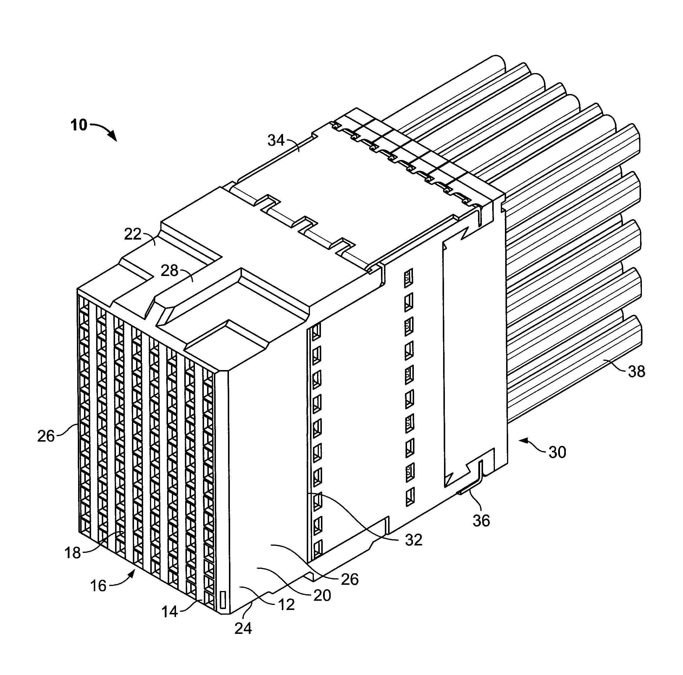
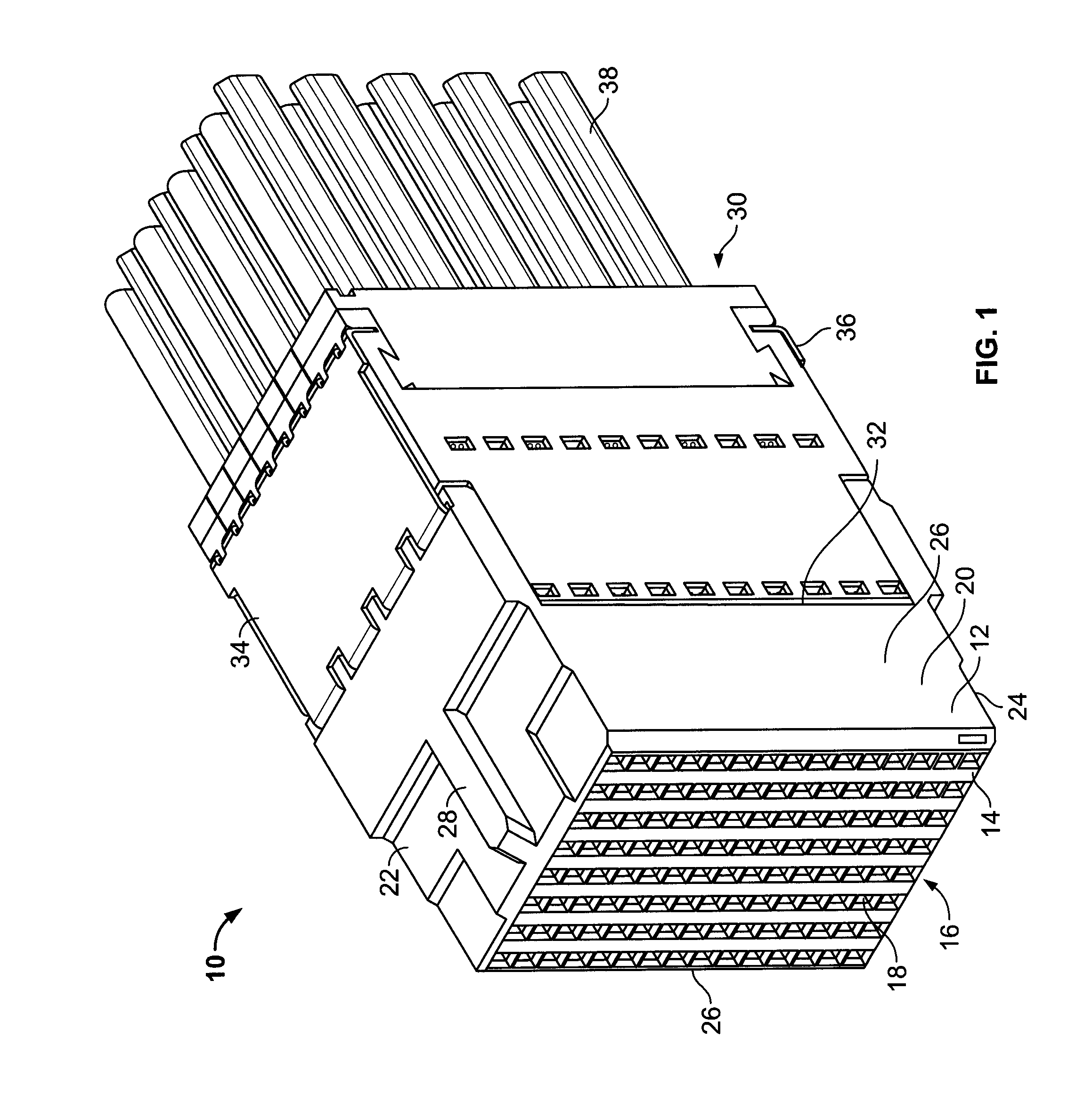
[0023]FIG. 1 is a front perspective view of a receptacle connector assembly 10 formed in accordance with an exemplary embodiment. The receptacle connector assembly 10 is matable with a header connector assembly (not shown) to create a differential connector system. For example, the header connector assembly may be a Z-PACK TinMan header connector, which is commercially available from Tyco Electronics. While the receptacle connector assembly 10 will be described with particular reference to a high speed, differential cable connector, it is to be understood that the benefits herein described are also applicable to other connectors in alternative embodiments. The following description is therefore provided for purposes of illustration, rather than limitation, and is but one potential application of the subject matter herein.

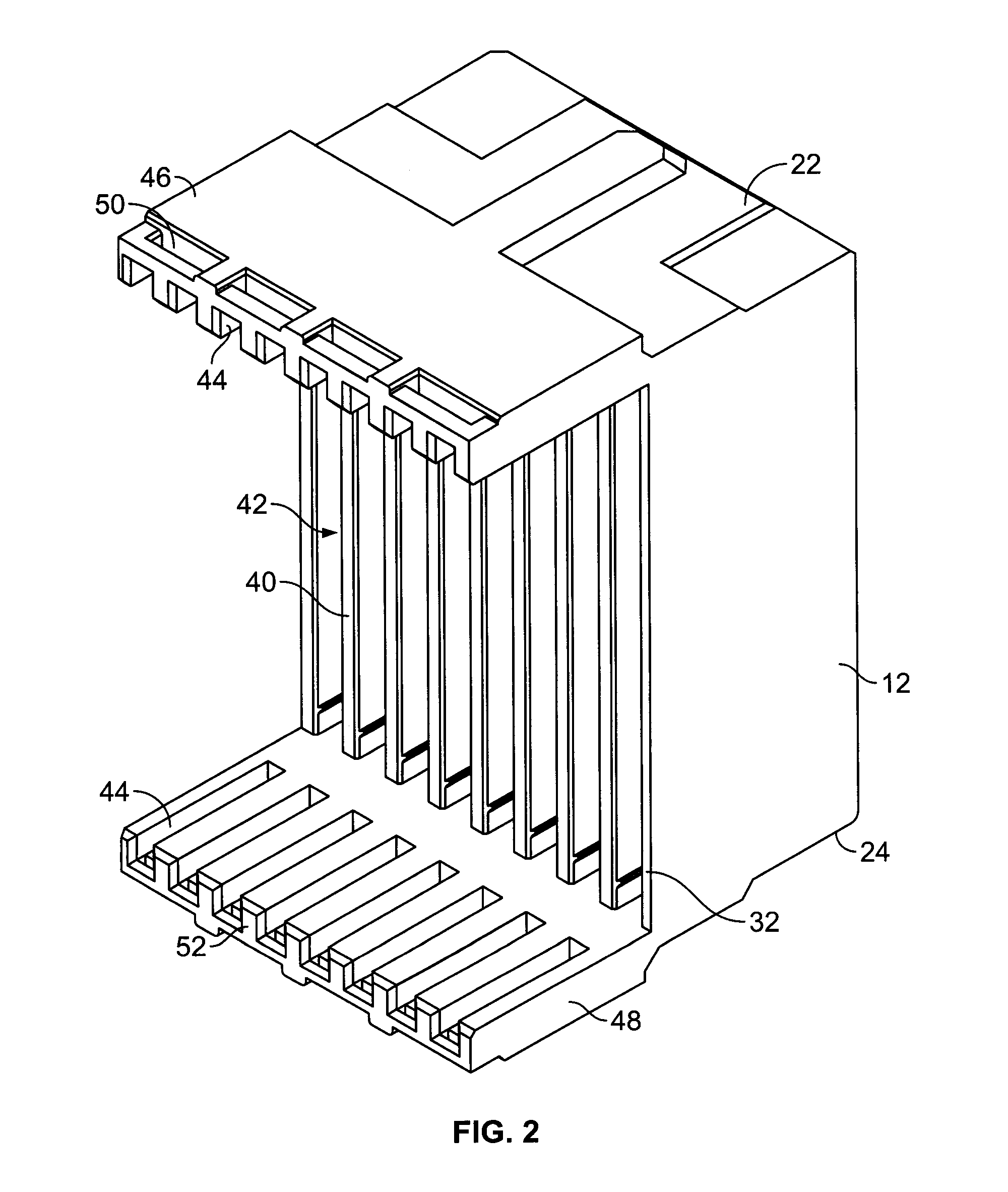
[0024]As illustrated in FIG. 1, the receptacle connector assembly 10 includes a dielectric housing 12 having a forward mating end 14 that includes a mating interfac...


PUM


Abstract

A connector assembly includes a housing having support walls extending between a loading end and a mating end that define a mating interface. A contact module is received within the housing through the loading end, and the contact module includes contacts, a body and a plurality of conductors held by the body. The conductors extend between mating ends and wire terminating ends, and the contacts extend from the mating ends of the conductors at the mating interface of the housing. The wire terminating ends are configured to be terminated to individual wires of a cable. A clip has a first securing tab and a second securing tab, wherein the first securing tab is securely coupled to the housing and the second securing tab is securely coupled to the contact module. The clip securely retains the contact module within the housing.

Description

BACKGROUND OF THE INVENTION[0001]The subject matter herein relates generally to cable connector assemblies, and more particularly, to high speed, differential cable connector assemblies.[0002]With the ongoing trend toward smaller, faster, and higher performance electrical components such as processors used in computers, routers, switches, etc., it has become increasingly desirable for the electrical interfaces along the electrical paths to also operate at higher frequencies and at higher densities with increased throughput. For example, performance demands for video, voice and data drive input and output speeds of connectors within such systems to increasingly faster levels.[0003]Electrical connectors typically are arranged to be connected to complementary connector halves to form connector pairs. One application environment that uses such electrical connectors is in high speed, differential electrical connectors, such as those common in the telecommunications or computing environme...

Claims


Application Information

Patent Timeline
Patent Type & Authority Applications(United States)
IPC IPC(8): H01R13/627
CPCH01R13/514H01R13/506
Inventor DAVIS, WAYNE SAMUELWHITEMAN, JR., ROBERT NEILLACHMAN, JULIA
Owner TE CONNECTIVITY CORP
Why Eureka
Try Eureka