

Pressing Member, Ultrasonic Probe and Ultrasonic Diagnosing Device
a technology of ultrasonic probe and ultrasonic diagnosis, which is applied in the direction of mechanical vibration separation, instruments, catheters, etc., can solve the problems of noise in the elastic image, the effort of further improving the press plate, etc., and achieve the effect of high-precision elastic image and efficient image diagnosis
- Summary
- Abstract
- Description
- Claims
- Application Information
AI Technical Summary
Benefits of technology
Problems solved by technology
Method used
Image

Examples
first embodiment
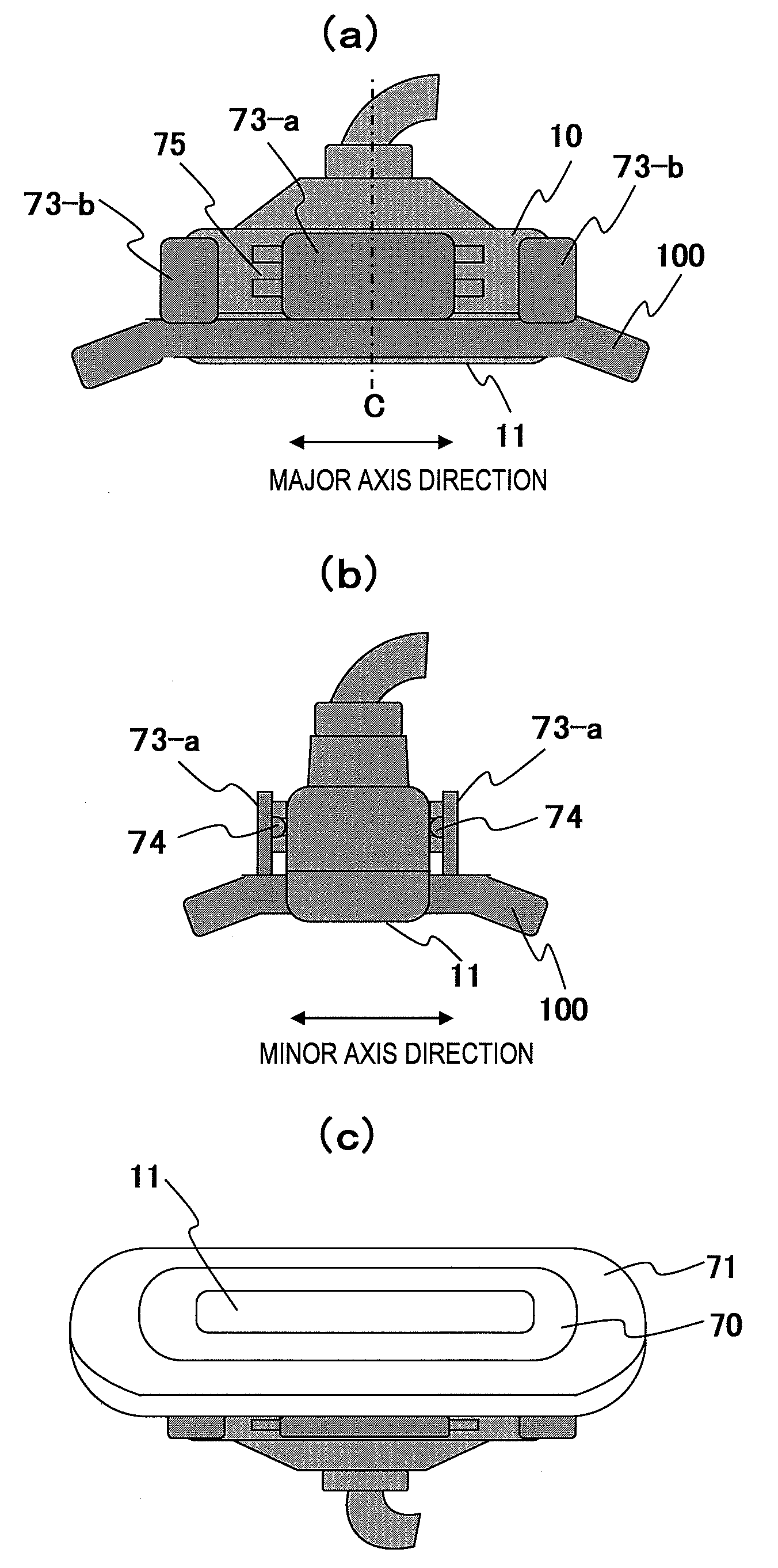
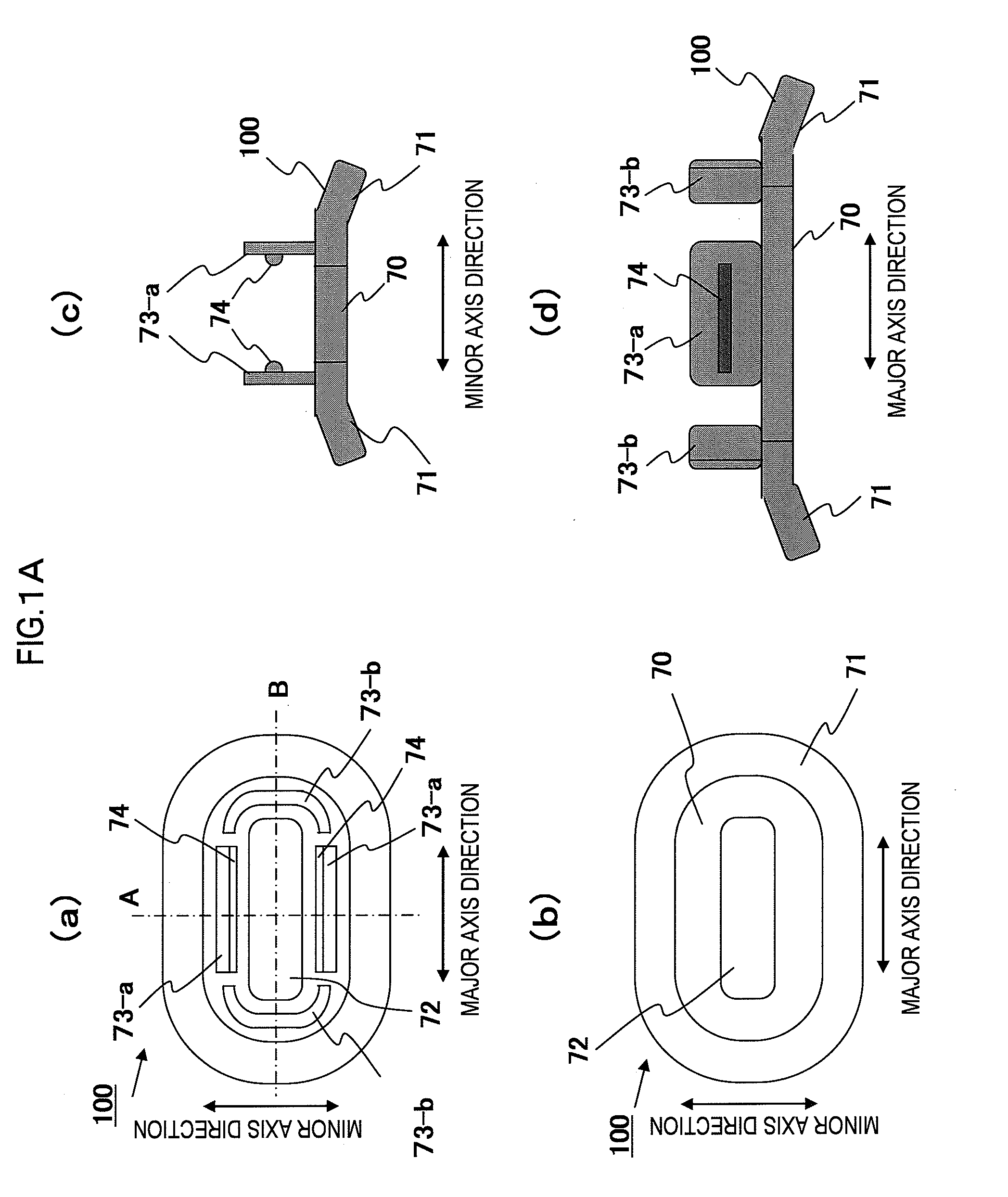
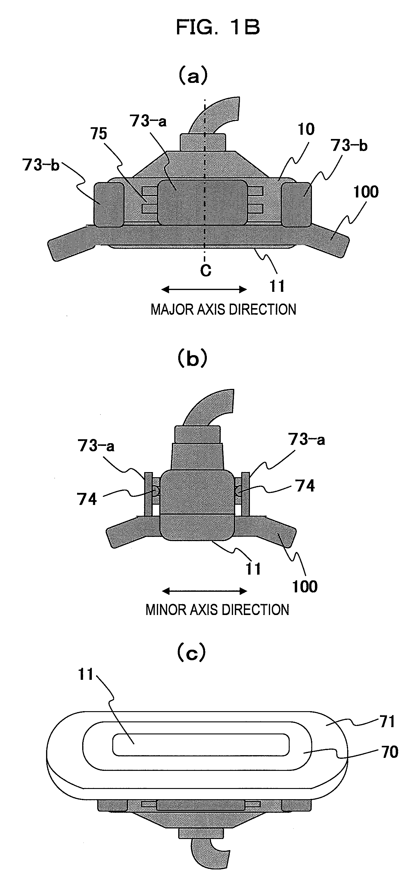
[0043]A first embodiment according to the present invention will be described. First, the shape of the pressing member of this embodiment will be described. The pressing member of this embodiment is characterized by comprising a first member for transferring pressing force in a direction parallel to the pressing direction to the subject, and a second member for transferring pressing force in a direction different from the pressing direction.
[0044]The second member is preferably designed as follows. That is, it is formed so as to extend to the edge portion of the first member. Furthermore, it is designed so that the transferring direction of the pressing force faces the center portion side of the first member so as to intersect with the pressing direction. Furthermore, considering the perspective of the subject, the second member is formed so as to press a part of the subject pressed by the first member so that the part of the subject is prevented from being pushed out in a direction...
second embodiment
[0065]Next, a second embodiment of the present invention will be described with reference to FIG. 2(b). FIG. 2(b) shows the probe 10 on which the pressing plate 100 is mounted when the probe 10 is viewed in the major axis direction. A pressing plate 110 having an arcuate lower surface is detachably secured to the ultrasonic wave scanning face side of the probe 10. The difference from the first embodiment resides in that the pressing plate 110 has an arcuate shape.
[0066]The arcuate pressing plate 110 is designed so that the slant angle gradually grows steeper to the subject side as the position shifts to the edge portion, and the contact surface with the subject 5 has a concave shape. For example, the pressing plate has a concave curve as shown in FIG. 1D(b). Therefore, the displacement vector 102 of the edge portion is inclined to the inside (that is, the center portion side of the probe 10) as compared with the displacement vector 102 at the center portion.
[0067]As described above,...
third embodiment
[0070]Next, a third embodiment of the present invention will be described with reference to FIGS. 3(a) (b). FIG. 3(a) shows a pressing plate 152 for pressing the subject 5 and the probe 10 when they are viewed in the major axis direction. FIG. 3(b) shows the pressing plate 152 and the probe 10 when they are viewed in the minor axis direction. The flat-plate type pressing plate 152 is detachably secured to the ultrasonic wave scanning face side of the probe 10. The difference from the first embodiment and the second embodiment resides in that the pressing plate 152 is of a flat-plate type and the size of the pressing plate is suitable for the site being examined of the subject 5.
[0071]An observation site 150 of the subject 5 is abreast, for example. The pressing plate 152 has the size suitable for the observation site 150, and the surface area of the pressing face is larger than the case where the observation site 150 is pressed in the major axis and minor axis directions by only the...
PUM
 Abstract
Description
Claims
Application Information