Method and apparatus for forming motor winding conductors

a technology of winding conductors and winding wires, which is applied in the direction of electrical apparatus, dynamo-electric machines, synchronous machines, etc., can solve the problems of high labor intensity, slow and laborious process described above, and not suitable for mass produced motors

Active Publication Date: 2009-07-16
TECNOMATIC
View PDF21 Cites 56 Cited by
  • Summary
  • Abstract
  • Description
  • Claims
  • Application Information

AI Technical Summary

Problems solved by technology

However, the procedure described above is slow and highly labor intensive, and not suitable for a mass produced motor.

Method used


Image

  • Method and apparatus for forming motor winding conductors
  • Method and apparatus for forming motor winding conductors
  • Method and apparatus for forming motor winding conductors

Examples


Embodiment Construction

[0024]In the description of preferred embodiments of the present invention to follow, the terms “flat”, “square”, “rectangular” and “straight” will be used. Unless otherwise apparent, such terms are used in accordance with the definitions thereof set forth in the prior art section above.

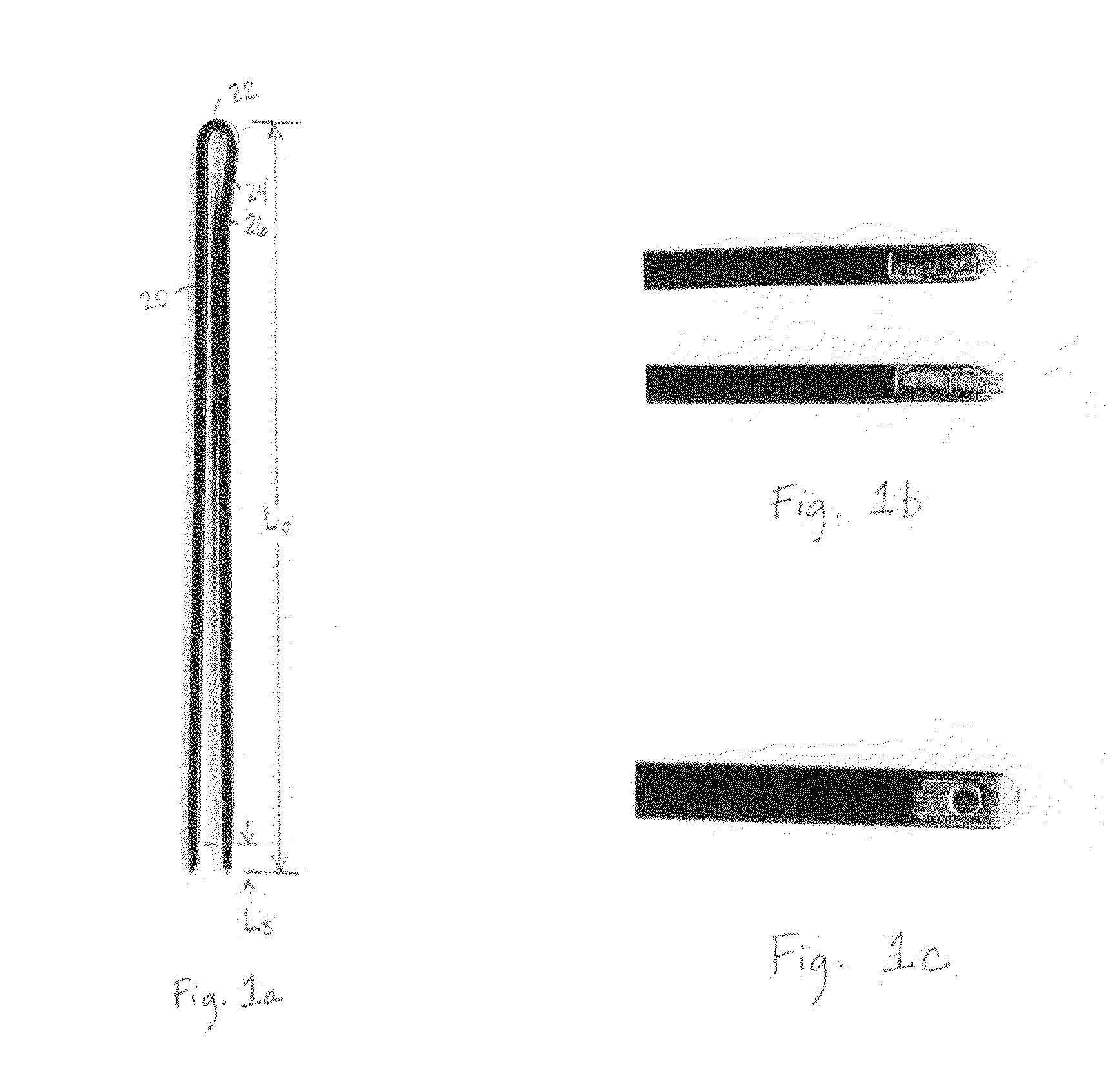
[0025]The purpose of the present invention is to automatically twist hairpin shaped conductors of rectangular wire as may be used, by way of example, as part of a process for automatically manufacturing motors of the type described above, to form rotor and stator conductors. An exemplary hairpin conductor may be seen in FIG. 1a and is characterized by an overall length L0, formed by bending a rectangular insulated conductor with the ends thereof being stripped of insulation over the length LS. The typical insulation on the hairpin conductors is a typical motor or solenoid winding insulation well known in the motor art. In a preferred embodiment of the invention, one side 20 of the hairpin conductor a...


PUM

PropertyMeasurementUnit
thicknessaaaaaaaaaa
widthaaaaaaaaaa
lengthsaaaaaaaaaa

Abstract

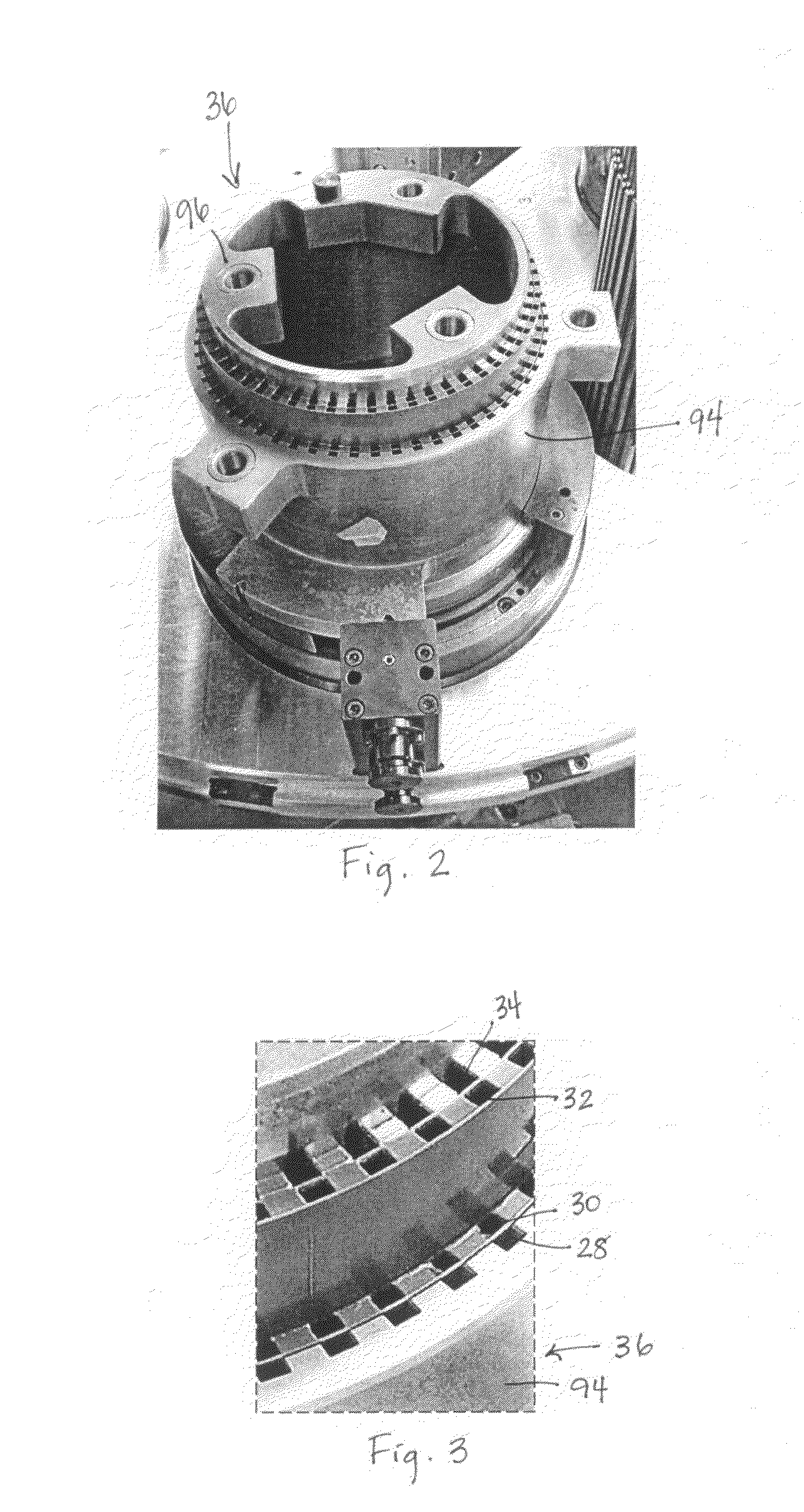
Method and apparatus for forming motor winding conductors rectangular conductor wire. The method comprises populating with hairpin shaped conductors, most of a forming fixture having a plurality of pockets distributed in equal number in one or more pairs of adjacent circles, each concentric with a center of the forming fixture, at least one member defining each of the pockets in one of each pair of adjacent circles being rotatable, at least through a limited angle, with respect to a member defining the pockets in the other of the respective pair of adjacent circles, the hairpin conductors each having first and second legs integrally joined by a loop at one end thereof, with one leg of each hairpin conductor in a respective one of the pockets in a pair of adjacent circles, and rotating in a first direction, relative to each other, the members defining the pockets in each pair of circles through a predetermined angle, to permanently separate the two legs of each hairpin conductor without substantial rotation of each leg of the hairpin conductors relative to its respective pocket. Various additional features are disclosed.

Description

BACKGROUND OF THE INVENTION[0001]1. Field of the Invention[0002]The present invention relates to the field of electric motors.[0003]2. Prior Art[0004]Tecnomatic S.p.A., assignee of the present invention, has in the past made a limited number of motor motors and D.C. motor rotors using flat or square wire for the windings. In that regard, it is to be noted that as used herein, “flat” or “square” wire means wire having four substantially flat sides, each joined to adjacent sides, typically by a rounded edge. In the case of square wire, the wire may be formed in the square shape and then coated with typical winding insulation, or in some cases, pre-coated round wire has been rolled into the square shape. Rolling of round wire to a square shape has definite limits if the insulation is not to be damaged, though smaller rounded edges may be achieved if the wire is first formed by drawing or otherwise formed into the square shape and then coated. Even if the wire is first formed in the des...

Claims


Application Information

Patent Timeline
Patent Type & Authority Applications(United States)
IPC IPC(8): H02K15/00
CPCH02K15/0428Y10T29/49009Y10T29/49012
Inventor GUERCIONI, SANTE
Owner TECNOMATIC
Why Eureka
Try Eureka