Variable Planing Inflatable Hull System

a technology of inflatable hull and variable planing, which is applied in the direction of special-purpose vessels, vessel construction, transportation and packaging, etc., can solve the problems of loss of efficiency, propulsion systems advantageous to shallow water operations, and ineffective use of existing vessels that use inflatable structures

Inactive Publication Date: 2009-07-16
MARINE ADVANCED RES
View PDF31 Cites 8 Cited by
  • Summary
  • Abstract
  • Description
  • Claims
  • Application Information

AI Technical Summary

Problems solved by technology

However, existing vessels that use inflatable structures generally do not effectively take advantage of all three aspects.
Also propulsion systems advantageous to shallow water ope

Method used


Image

  • Variable Planing Inflatable Hull System
  • Variable Planing Inflatable Hull System
  • Variable Planing Inflatable Hull System

Examples


Embodiment Construction

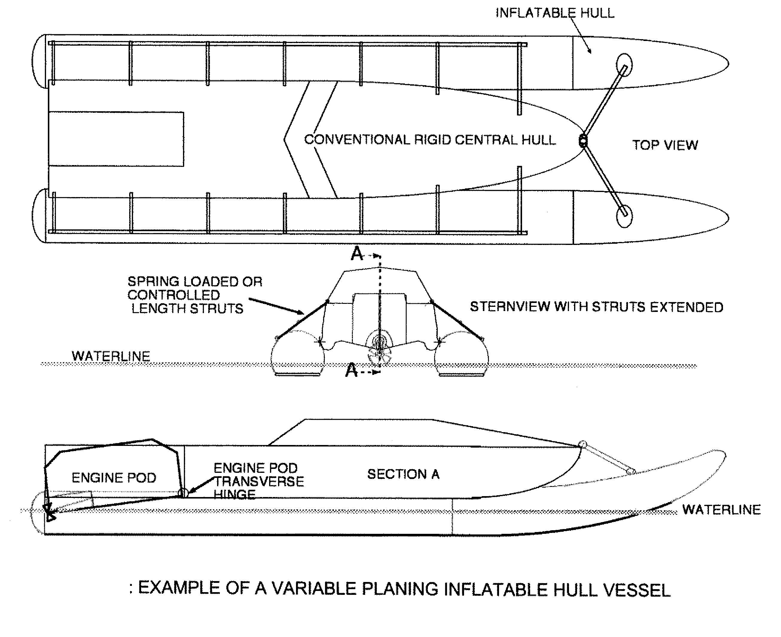
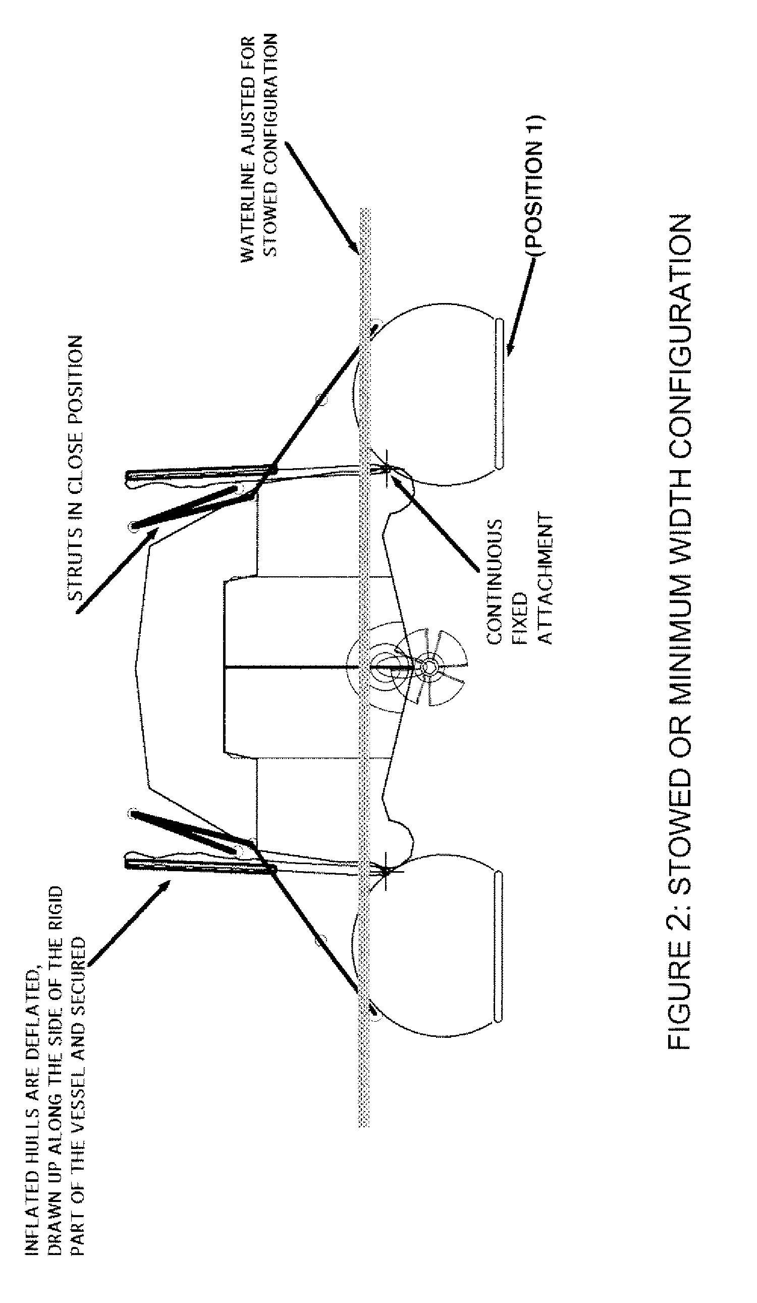
[0016]This invention provides for a vessel that utilizes a variable planing inflatable hull system in order to increase speed, efficiency, acceleration, shock absorption and maneuverability. A hinged engine pod can be added to ensure proper propulsion. The engine pod will itself follow the water surface, assuring that the propeller remains in the water under all operating conditions, but could be withdrawn up against the central hull section when not in use. Such vessel can also reduce its footprint considerably using this technique, so that it can be stowed and shipped in a smaller space. For example, a vessel with a 50′L×17′W×8′H configuration could be reduced to 40′L×9′W×6′H and transported in the cargo hold of a C-130 aircraft.

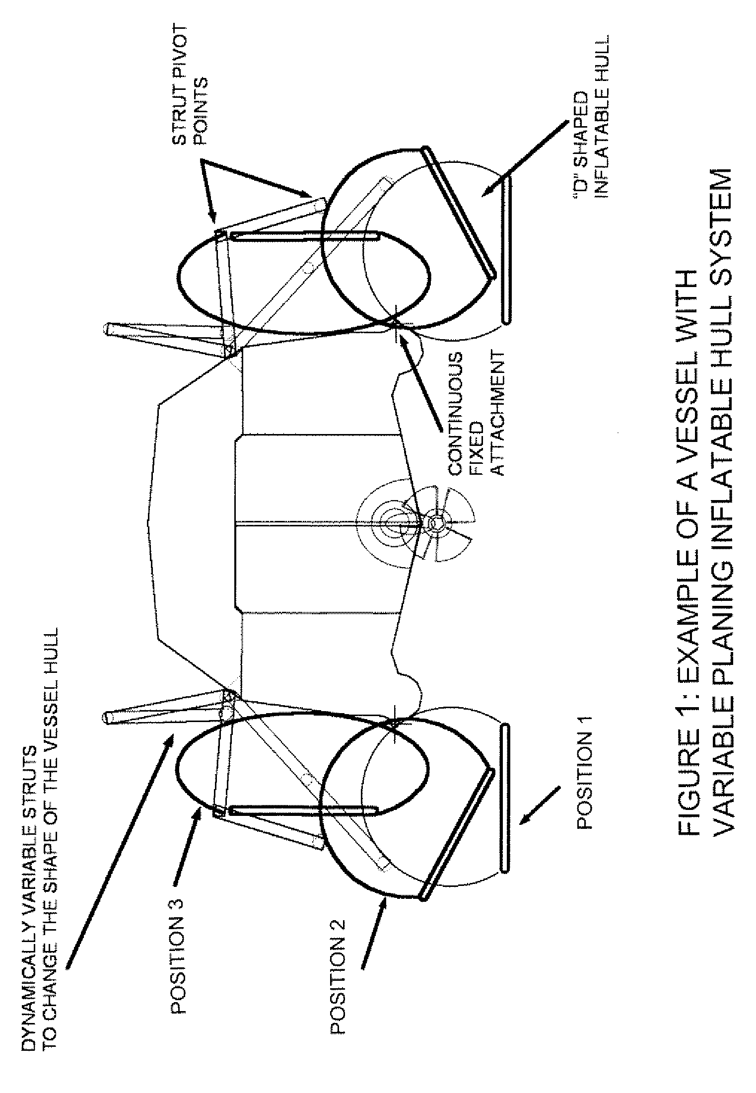
[0017]FIG. 1 shows the “D” shaped inflatable air chambers attached to a more conventional boat hull, typically a rigid (in comparison to the inflatable hull sections) such as may be fabricated of fiberglass or other composite materials or metal. We call th...


PUM


Abstract

Variable planing inflatable hull system having a planing surface on inflatable hulls at the side and disposable central hull. The central hull is typically a rigid hull, with the inflatable hulls providing low wetted area planing surfaces for speed, shock absorbing and efficiency of the vessels. Various embodiments are disclosed.

Description

CROSS-REFERENCE TO RELATED APPLICATION[0001]This application claims the benefit of U.S. Provisional Patent Application No. 61 / 013,482 filed Dec. 13, 2007.BACKGROUND OF THE INVENTION[0002]1. Field of the Invention[0003]The present invention relates generally to inflatable marine vessel design.[0004]2. Prior Art[0005]Inflatable hulls offer stability, buoyancy and shock mitigation. However, existing vessels that use inflatable structures generally do not effectively take advantage of all three aspects. For example, RIBs (rigid inflatable boats) use the stability and buoyancy of the inflatable hull but rely on a separate rigid bottom for the planing surface.[0006]Also propulsion systems advantageous to shallow water operations, e.g. surface drives and jets, encounter loss of efficiency because, in certain combinations of speed and seaway, the propellers or the jets suction come out of the water.[0007]Improvements in vessels with inflatable hulls are disclosed in U.S. Pat. No. 6,874,439 ...

Claims


Application Information

Patent Timeline
IPC IPC(8): B63B1/14B63B1/10
CPCB63B1/20B63B39/005B63B7/082
Inventor GUNDERSEN, MARK
Owner MARINE ADVANCED RES
Why Eureka
Try Eureka