

Method of noncontact dispensing of viscous material
A viscous material, non-contact technology, used in devices for applying liquid to surfaces, coatings, printed circuit manufacturing, etc., can solve problems such as excessive thermal pressure, erosion, etc., to reduce production costs and product costs, reduce size , the effect of reducing the number of allocation cycles
- Summary
- Abstract
- Description
- Claims
- Application Information
AI Technical Summary
Problems solved by technology
Method used
Image

Examples
Embodiment Construction
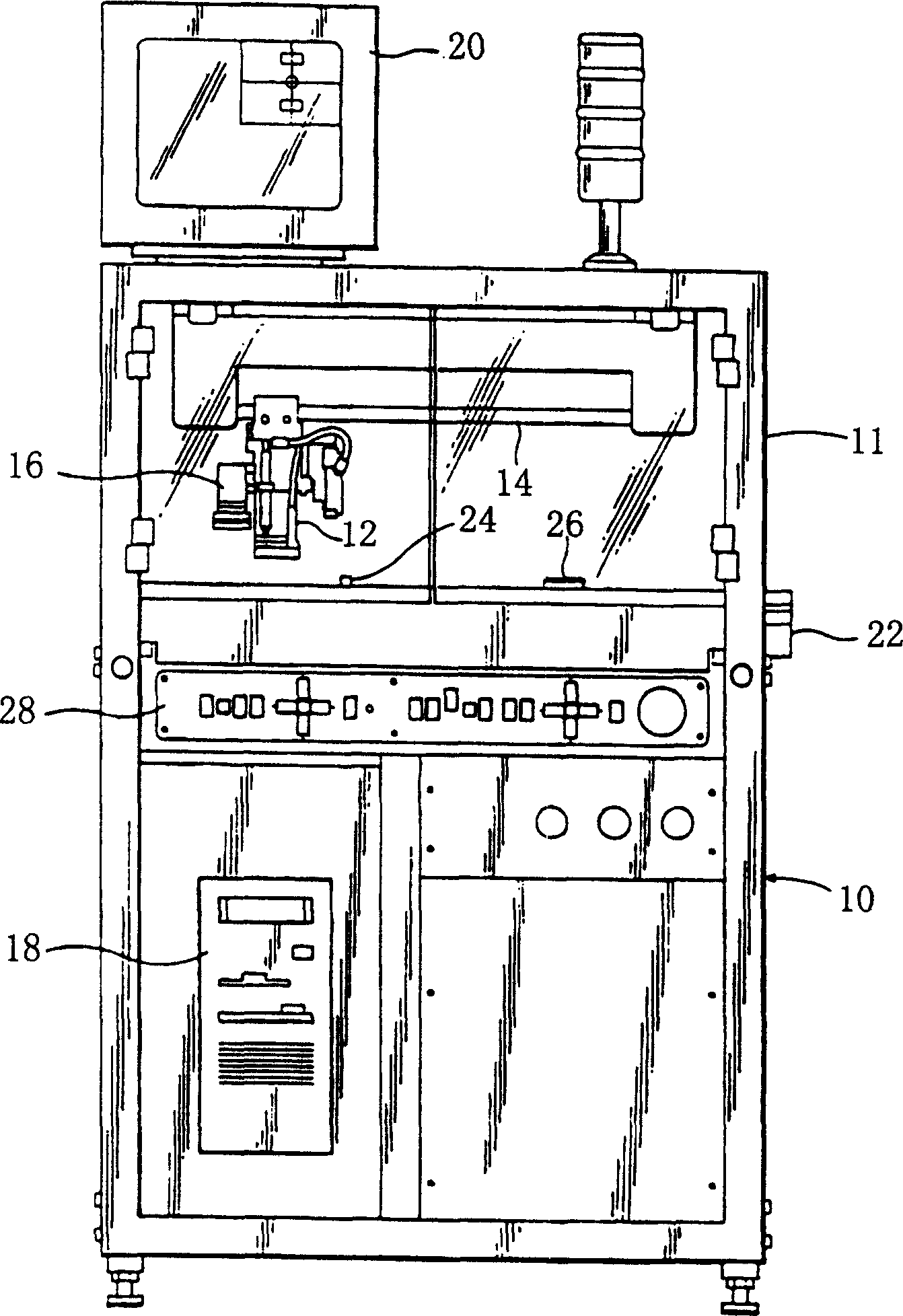
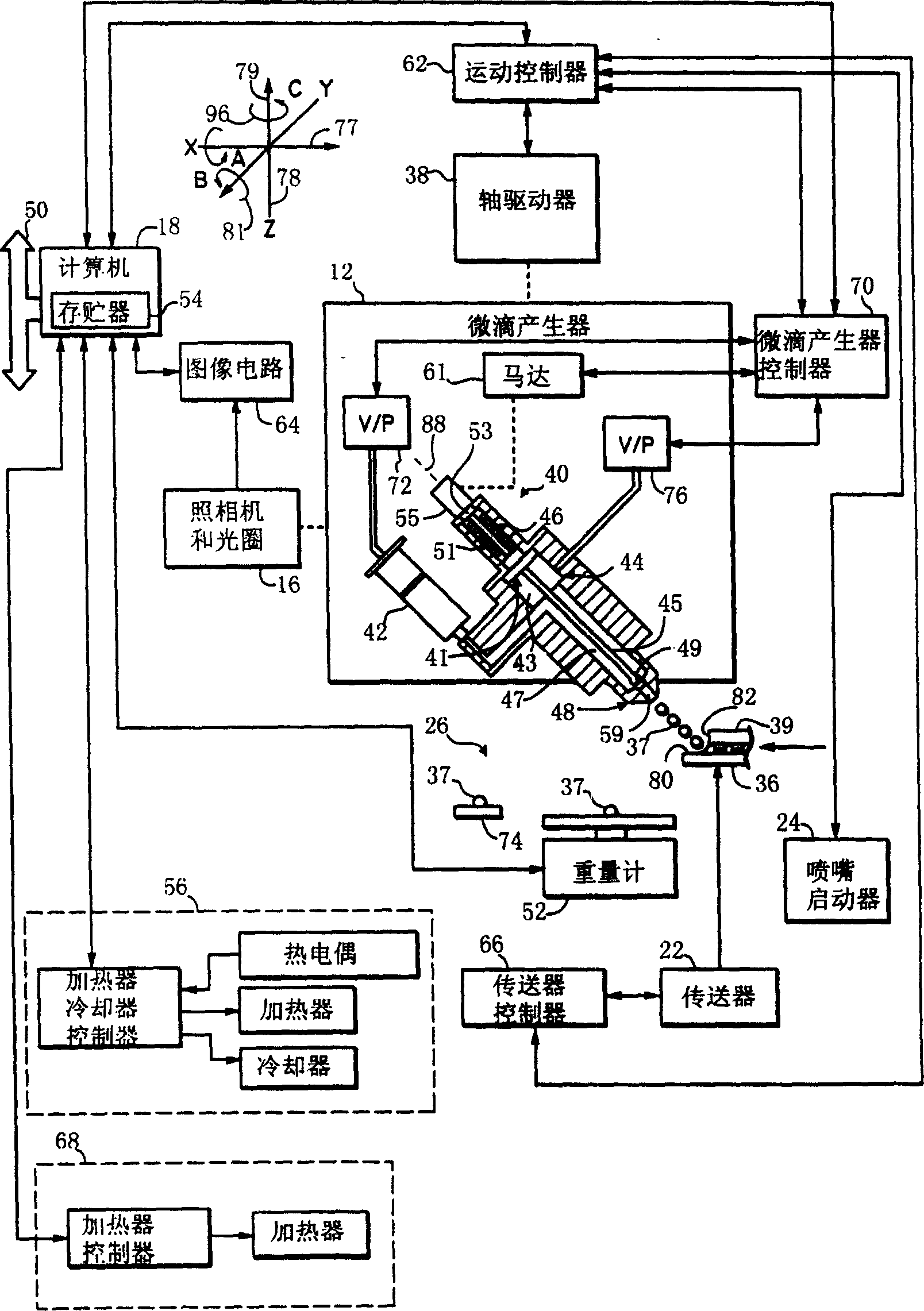
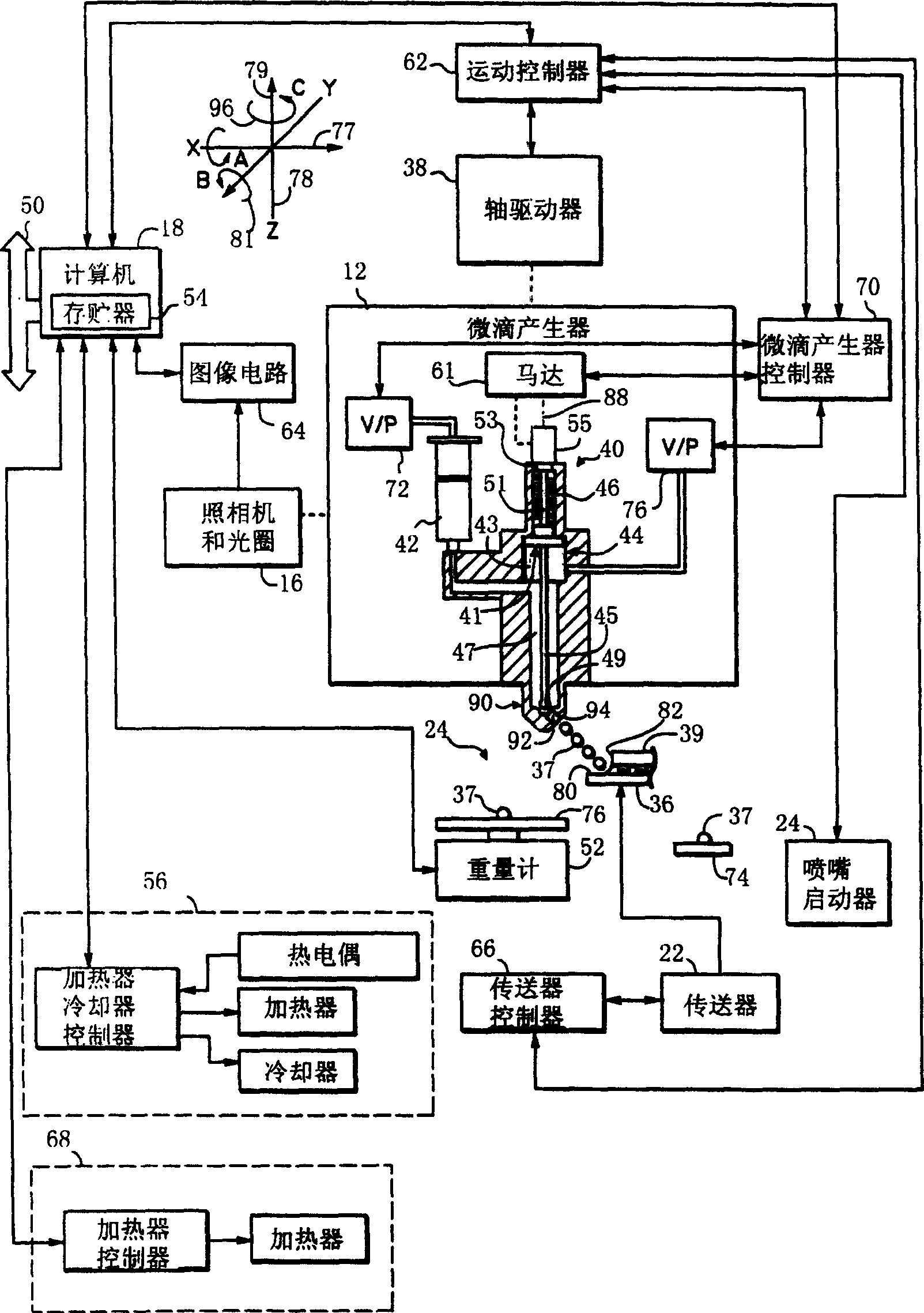
[0021] figure 1 is a schematic diagram of a computer controlled non-contact viscous material injection system 10, for example, the commercially available "AXIOM" X-20 series from Asymtek of Carlsbad, California. A droplet generator 12 is mounted on a Z-axis drive suspended from an X,Y positioner 14 in a known manner. The X,Y positioner 14 is mounted on the frame 11 and defines first and second non-parallel axes of motion. The X, Y positioner comprises a cable drive connected in known manner to a pair of independently controllable stepper motors (not shown). A video camera and LED aperture assembly 16 is connected to the droplet generator 12 for movement along the X, Y and Z axes to check points and locate reference fiducials. The video camera and aperture assembly 16 may be of the type described in U.S. Pat. No. 5,052,338 "APPARATUS FOR DISPENSING VISCOUS MATERIALS ACONSTANT HEIGHT ABOVE A WORKPIECE SURFACE," the entire disclosure of which is incorporated herein by referenc...
PUM
 Abstract
Description
Claims
Application Information