Power saving uninterruptible power supply

Inactive Publication Date: 2009-07-16
CYBER POWER SYST
View PDF2 Cites 17 Cited by
  • Summary
  • Abstract
  • Description
  • Claims
  • Application Information

AI Technical Summary

Benefits of technology

[0009]An objective of the present invention is to provide a power saving uninterruptible power supply (UPS). The power saving uninterruptible power supply (UPS) in accordance with the present invention not only provides emergency power supply, but also effectively resolves the drawback of over-consuming power.

Problems solved by technology

Hence the overall efficiency of the transformer 60 consumes 50% of the power, which wastes power.
However, the abnormal AC power supply time is usually much shorter than the normal AC power supply time.

Method used


Image

  • Power saving uninterruptible power supply
  • Power saving uninterruptible power supply
  • Power saving uninterruptible power supply

Examples


Embodiment Construction

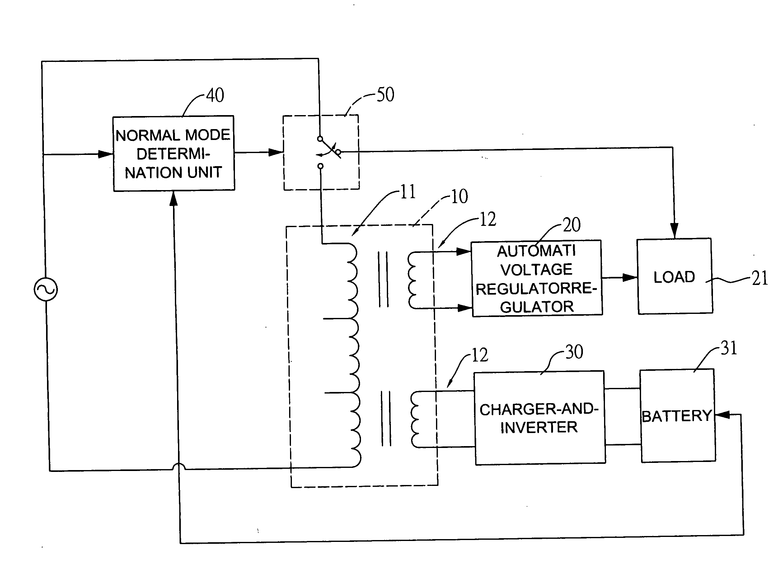
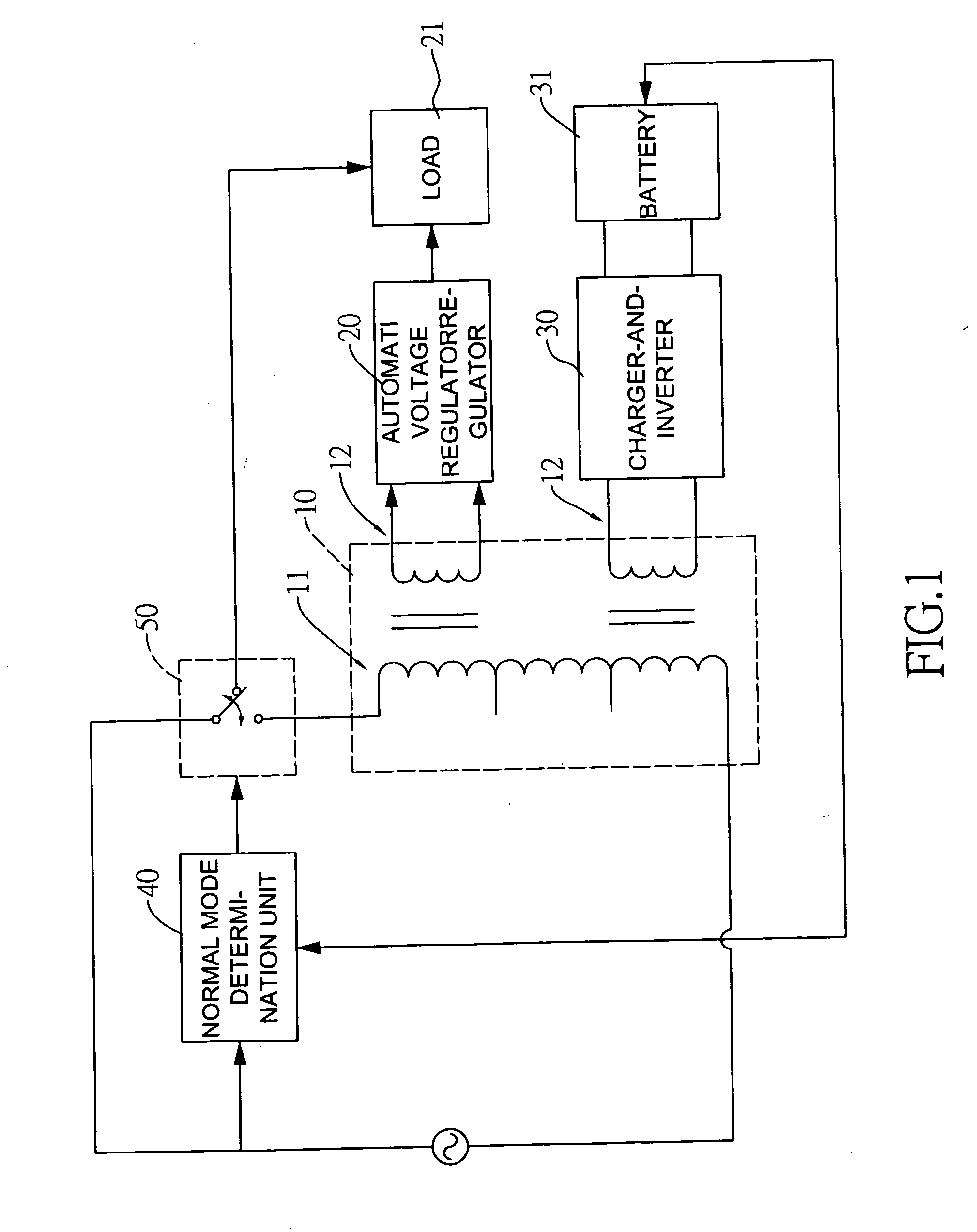
[0019]With reference to FIG. 1, a power saving uninterruptible power supply (UPS) in accordance with the present invention has a transformer 10, an automatic voltage regulator (AVR) 20, a charger-and-inverter 30, a normal mode determination unit 40 and an electric switch 50. The transformer 10 has a primary side 11 and a secondary side 12. The primary side 11 is coupled to an alternating current (AC) power source.

[0020]An alternating current (AC) input terminal of the AVR 20 is coupled to the secondary side 12 of the transformer 10 to acquire an inducted AC power source. Then the AVR 20 regulates the inducted AC power source to output to a load 21.

[0021]The charger-and-inverter 30 is coupled to the secondary side 12 of the transformer 10. Hence the charger-and-inverter 30 acquires a recharged power source to convert to a recharged current. Then the charger-and-inverter 30 charges the battery 31 or also converts electricity of the battery 31 to the AC power source to output to the tr...


PUM


Abstract

The power saving uninterruptible power supply (UPS) has a transformer, an automatic voltage regulator (AVR), a charger-and-inverter, a normal mode determination unit and an electric switch. The transformer has a primary side and a secondary side. The primary side is coupled to an alternating current (AC) power source. An AC input terminal of the AVR is coupled to the secondary side of the transformer to acquire an inducted AC power source to regulate the inducted AC power source to output to a load. The charger-and-inverter is coupled to the secondary side of the transformer to acquire a recharged power source to convert to a recharged current. The normal mode determination unit is coupled to the AC power source and the battery to detect a power supply status of the AC power source and battery capacity, so as to further determine whether current operation is normal.

Description

BACKGROUND OF THE INVENTION[0001]1. Field of the Invention[0002]The invention relates in general to an uninterruptible power supply (UPS), and more particularly to a power saving UPS that has low power consumption.[0003]2. Description of the Related Art[0004]With reference to FIG. 3, a conventional uninterruptible power supply (UPS) has a transformer 60, an automatic voltage regulator (AVR) 70 and a charger and inverter 80.[0005]The transformer 60 has a primary side 61 and a secondary side 62. The primary side 11 is coupled to an alternating current (AC) power source.[0006]An alternating current (AC) input terminal of the AVR 70 is coupled to the secondary side 62 of the transformer 60 to acquire an inducted AC power source. Then the AVR 70 regulates the inducted AC power source to output to a load 71.[0007]The charger-and-inverter 80 is coupled to the secondary side 62 of the transformer 60 to acquire a recharged power source to convert to a recharged current. Then the charger-and-...

Claims


Application Information

Patent Timeline
IPC IPC(8): H02J9/06H02J7/00
CPCH02J9/062Y04S20/20Y02B70/30
Inventor HO, LIEN-HSUNYEH, SHOU-TINGHSIEH, HUNG-MING
Owner CYBER POWER SYST
Why Eureka
Try Eureka