Power saving uninterruptible power supply

a power supply and power saving technology, applied in the field of uninterruptible power supply, can solve the problems of large size, unstable or interrupted utility power, and b> can still operate, and achieve the effect of effectively solving the drawback of over-consuming power

Active Publication Date: 2011-03-22
CYBER POWER SYST
View PDF3 Cites 3 Cited by
  • Summary
  • Abstract
  • Description
  • Claims
  • Application Information

AI Technical Summary

Benefits of technology

[0010]An objective of the present invention is to provide a power saving uninterruptible power supply (UPS). The power saving uninterruptible power supply (UPS) in accordance with the present invention not only provides emergency power supply, but also effectively resolves the drawback of over-consuming power.
[0011]The power saving UPS has a first and second switches, an energy spared switch, a transformer, an automatic voltage regulator (AVR), a charger-and-inverter, a normal mode determination unit and an electric switch. When the utility power is stable, the first and second switches are connected together to supply the utility power to a load. At the time, the energy spared switch is physically disconnected with the utility power and the transformer and the AVR. Therefore, the transformer and AVR do not consume more energy of the utility power and the transforming efficiency of the UPS in accordance with the present invention is increased.

Problems solved by technology

Therefore, the load 65 can still operate normally even the utility power is unstable or interrupted.
However, the AVR has a huge size, low transforming efficiency etc. drawbacks.

Method used


Image

  • Power saving uninterruptible power supply
  • Power saving uninterruptible power supply
  • Power saving uninterruptible power supply

Examples


Embodiment Construction

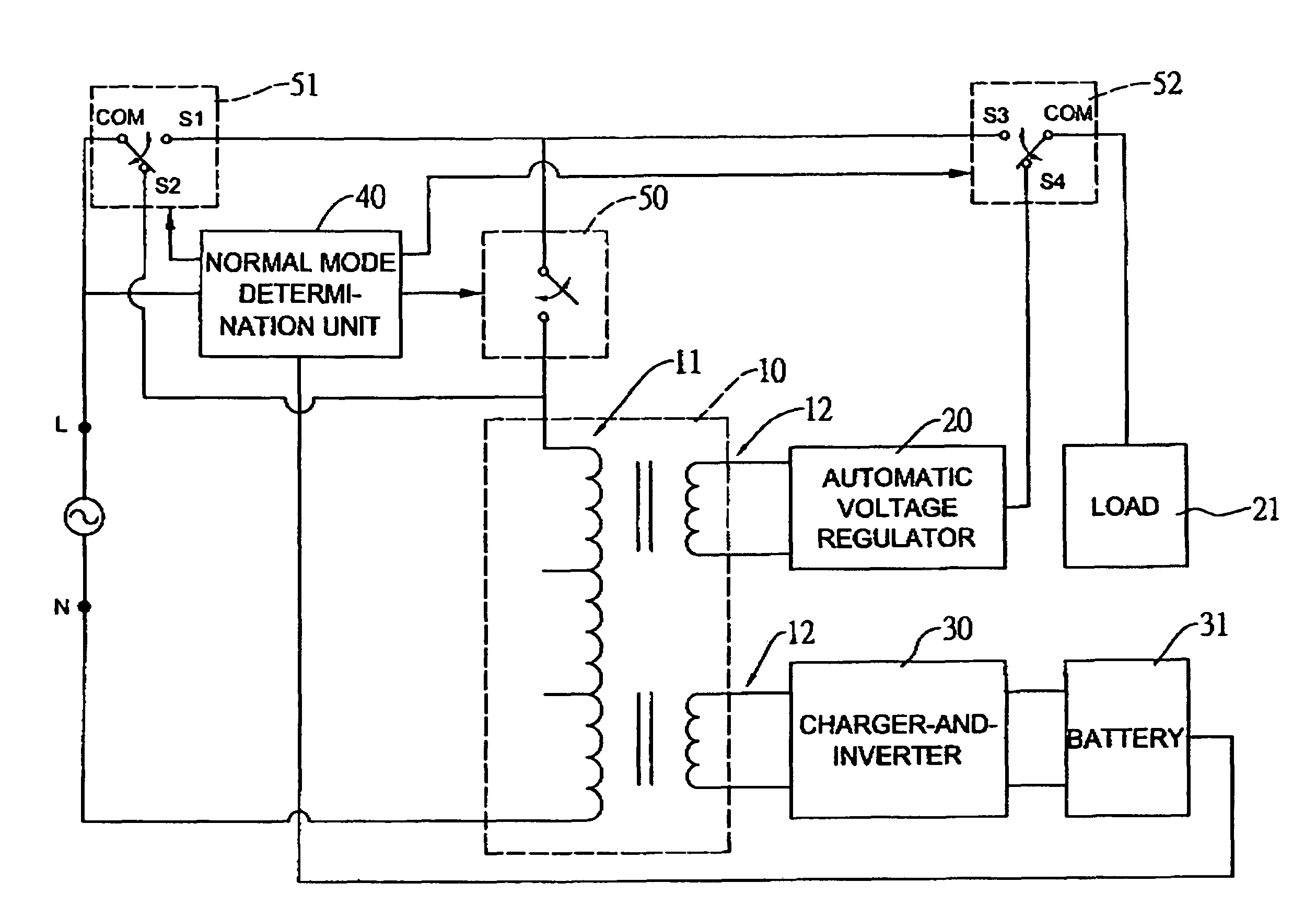
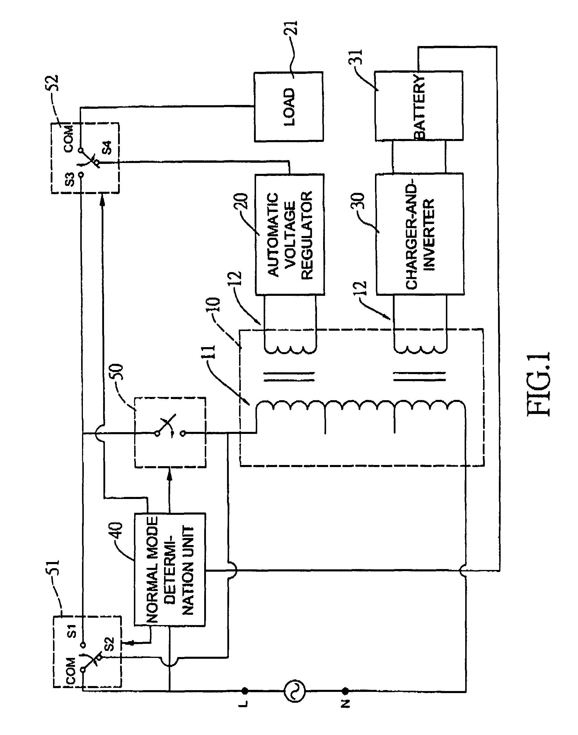
[0016]With reference to FIG. 1, a power saving uninterruptible power supply (UPS) in accordance with the present invention has a power coupling terminals L,N, a transformer 10, an automatic voltage regulator (AVR) 20, a charger-and-inverter 30, a normal mode determination unit 40, a first switch 51, a second switch 52 and an energy spared switch 50. The transformer 10 has a primary winding 11 and a secondary winding 12.

[0017]The power coupling terminals L, N have a line terminal L and a neutral terminal N and are coupled to a utility power. One end of the transformer 10 is connected to one of the power coupling terminals L through the energy spared switch 50. That is, two nodes of the energy spared switch 52 are respectively connected to the end of the primary winding 11 and the utility power. The other end of the transformer 10 is connected to the other power coupling terminals N. In the embodiment, the energy spared switch 50 is connected between the line terminal L and one end of...


PUM


Abstract

The power saving uninterruptible power supply (UPS) has a first and second switches, an energy spared switch, a transformer, an automatic voltage regulator (AVR), a charger-and-inverter, a normal mode determination unit and an electric switch. When the utility power is stable, the first and second switches are connected together to supply the utility power to a load. At the time, the energy spared switch is physically disconnected with the utility power and the transformer and the AVR. Therefore, the transformer and AVR do not consume more energy of the utility power and the transforming efficiency of the UPS is increased.

Description

[0001]The present invention is a continuation-in-part (CIP) application claiming the benefit of U.S. patent application Ser. No. 12 / 008,936 filed on Jan. 15, 2008 now abandoned.BACKGROUND OF THE INVENTION[0002]1. Field of the Invention[0003]The invention relates in general to an uninterruptible power supply (UPS), and more particularly to a power saving UPS that has low power consumption.[0004]2. Description of the Related Art[0005]In general, UPS has three types, a first one is on-line UPS, a second one is off UPS and a third one is line interactive UPS. With reference to FIG. 3, an improved on-line UPS 60 is disclosed by U.S. Pat. No. 5,229,650 and has a rectifier 61, an inverter 62, a charger 63, a battery 631 and a control signal generator 64. The rectifier 61 is coupled to a utility power and inputs of the inverter 62. The charger 63 is connected to the battery 631 and the utility power through a first switch SW1. The battery 631 is connected to the inputs of the inverter 62 th...

Claims


Application Information

Patent Timeline
Patent Type & Authority Patents(United States)
IPC IPC(8): H02J9/06
CPCH02J9/005H02J9/062Y02B70/30Y04S20/20
Inventor HO, LIEN-HSUNYEH, SHOU-TINGHSIEH, HUNG-MING
Owner CYBER POWER SYST
Why Eureka
Try Eureka