Object detection system with improved object detection accuracy

a technology of object detection and object detection accuracy, applied in the field of object detection systems, can solve the problems of deteriorating the detection accuracy of target objects, and affecting the detection accuracy of objects, and achieve the effect of higher object detection accuracy

Active Publication Date: 2009-07-23
DENSO CORP
View PDF17 Cites 18 Cited by
  • Summary
  • Abstract
  • Description
  • Claims
  • Application Information

AI Technical Summary

Benefits of technology

[0013]In view of the circumstances set force above, an object of an aspect of the present invention is to provide object detection systems capable of detecting target objects with a higher object detection accuracy as compared with the object detection accuracy of the conventional method set forth above.

Problems solved by technology

However, the method disclosed in the Patent Publication may deteriorate the detection accuracy for target objects.
Thus, the method disclosed in the Patent Publication may not detect that the second different area in which no target object is present is not a matching area in the input image with respect to the predetermined target pattern.
This may result in deteriorating the detection accuracy for target objects.
In addition, if the distribution profile of the target area in which the target object is present is different from the profile of an ideal normal distribution, the method disclosed in the Patent Publication may not detect that the target area in which the target object is present is a matching area in the input image with respect to the predetermined target pattern.
This also may result in deteriorating the detection accuracy for target objects.

Method used


Image

  • Object detection system with improved object detection accuracy
  • Object detection system with improved object detection accuracy
  • Object detection system with improved object detection accuracy

Examples


first embodiment

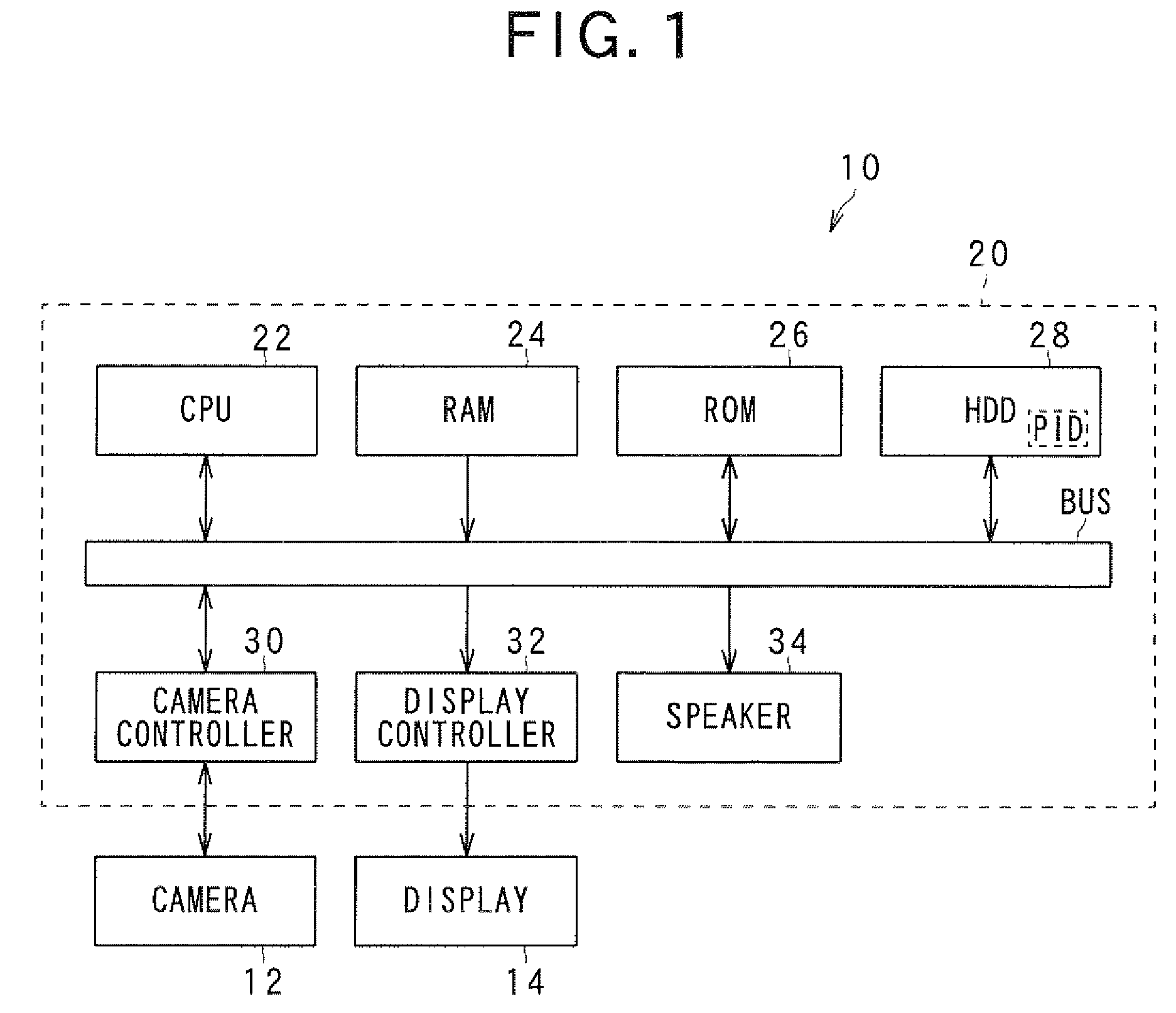
[0042]Referring to FIG. 1, there is illustrated an example of the overall structure of a driver assist system 10 according to a first embodiment of the present invention.

[0043]The driver assist system 10 includes a camera 12, a display 14, and a main unit 20.

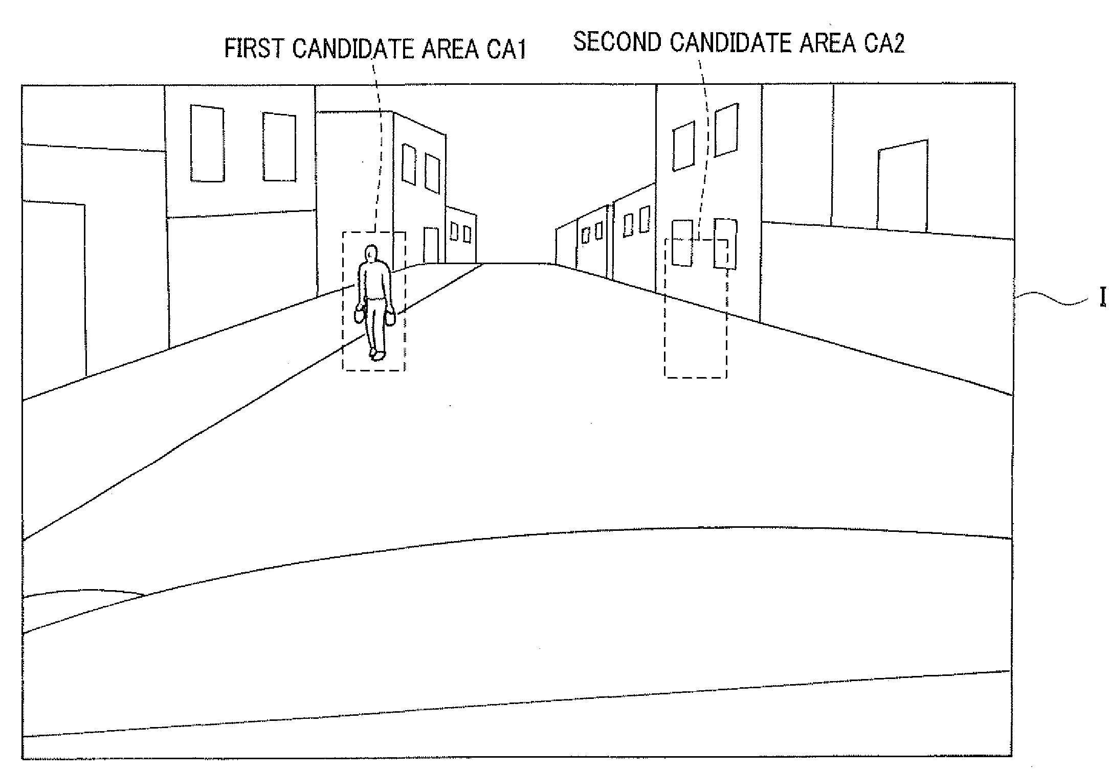
[0044]The camera 12 is mounted on one side of a body (outer shell) mounted on a frame of the vehicle and operative to periodically or continuously pick up a plurality of two-dimensional images (frame images) of a predetermined target region around the vehicle; this target region is defined based on the location of the camera 12 to be mounted on the vehicle body.

[0045]For example, each of the plurality of picked-up images consists of a matrix of m and n pixels each representing the light intensity (brightness) of a corresponding location thereof.

[0046]In the first embodiment, the camera 12 is mounted on a front side of the vehicle body. For example, the camera 12 is mounted on a bumper mounted on a front grille of a front panel (...

second embodiment

[0120]An example of the functional structure of a driver assist system 10A according to a second embodiment of the present invention will be described hereinafter. The hardware structure of the driver assist system 10A is substantially identical to that of the driver assist system 10 according to the first embodiment illustrated in FIG. 1. Like parts between the driver assist systems 10 and 10A according to the first and second embodiments, to which like reference characters are assigned, are omitted or simplified in description.

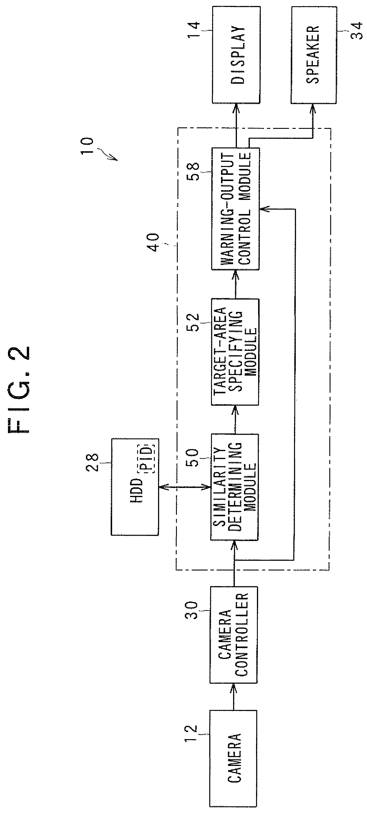
[0121]Referring to FIG. 6, the driver assist system 10A includes a functional module 40A implemented by the main unit 20.

[0122]The functional module 40A includes a similarity determining module 50A, a target-area specifying module 52A, and the warning-output control module 58. The similarity determining module 50A is operatively connected to the target-area specifying module 52A, and the target-area specifying module 52A is operatively connected to the warni...


PUM


Abstract

In a system for detecting a target object, a similarity determining unit sets a block in a picked-up image, and compares a part of the picked-up image contained in the block with a pattern image data while changes a location of the block in the picked-up image to determine a similarity of each part of the picked-up image contained in a corresponding one of the different-located blocks with respect to the pattern image data. A specifying unit extracts some different-located blocks from all of the different-located blocks. The determined similarity of the part of the picked-up image contained in each of some different-located blocks is equal to or greater than a predetermined threshold similarity. The specifying unit specifies, in the picked-up image, a target area based on a frequency distribution of some different-located blocks therein.

Description

CROSS REFERENCE TO RELATED APPLICATIONS[0001]This application is based on Japanese Patent Application 2008-010841 filed on Jan. 21, 2008. This application claims the benefit of priority from the Japanese Patent Application, so that the descriptions of which are all incorporated herein by reference.FIELD OF THE INVENTION[0002]The present invention relates to object detection systems for detecting a target object from a plurality of images picked up by a pickup device, such as a camera.BACKGROUND OF THE INVENTION[0003]Some types of conventional object detection methods are designed to detect a target object from a plurality of images picked up by a pickup device, such as a camera, using pattern-matching techniques.[0004]For example, Japanese Patent Application Publication No. H09-081726 discloses such an object detection method. The method disclosed in the Patent Publication matches the pattern of an input image in which a target object can exist with a predetermined target pattern co...

Claims


Application Information

Patent Timeline
Patent Type & Authority Applications(United States)
IPC IPC(8): G06K9/00G06K9/68
CPCG06K9/00805G06K9/6203G06V20/58G06V10/7515
Inventor WATANABE, AKIHIROSHIRAI, NORIAKIOSANAI, SATOSHI
Owner DENSO CORP
Why Eureka
Try Eureka