Speaker set for portable electronic device

a portable electronic device and speaker technology, applied in the direction of telephone set construction, transducer details, electrical transducers, etc., can solve the problems of reducing the maximum power of the speaker, the reduction of the loudness and the overall quality of sound, and the undesirable effect of increasing the size of the device to increase the size of the acoustic chamber of the speaker s

Inactive Publication Date: 2009-07-30
SHENZHEN FUTAIHONG PRECISION IND CO LTD +1
View PDF3 Cites 24 Cited by
  • Summary
  • Abstract
  • Description
  • Claims
  • Application Information

AI Technical Summary

Benefits of technology

[0006]For example, as shown in FIG. 4, a speaker set 100 for portable electronic devices includes a housing 10 and a speaker 19 incorporated in the housing 10. The housing 10 has a top surface11, a sidewall 13 extending upwards from the top surface 11, and a cavity 15 defined between the top surface 11 and the sidewall 13. A plurality of sound propagation holes 110 is defined in the top surface 11, and communicates with the cavity 15. The speaker 19 has a sound emanating surface 191. The speaker 19 is received in the cavity 15, with the sound emanating surface 191 thereof facing towards the top surface 11. An acoustic chamber is thus formed by the sound emanating surface 191 of the speaker 19 and the housing 10. Since the sound emanating surface 191 of the speaker 19 is disposed close to the top surface 11 of the housing 10, the acoustic chamber is small.

Problems solved by technology

As the device is reduced in size, the size of the acoustic chamber of the speaker set and the maximum power the speaker can handle are also accordingly reduced, resulting in both a reduction in loudness as well as a poorer overall quality of sound.
However, increasing the device size to increase the size of the acoustic chamber for the speaker set is very undesirable since it would strongly detract from the very characteristics that have helped to make these devices popular, namely size and weight.
Thus the size of the device is at odds with high capability sounds of the speaker.

Method used


Image

  • Speaker set for portable electronic device
  • Speaker set for portable electronic device
  • Speaker set for portable electronic device

Examples


Embodiment Construction

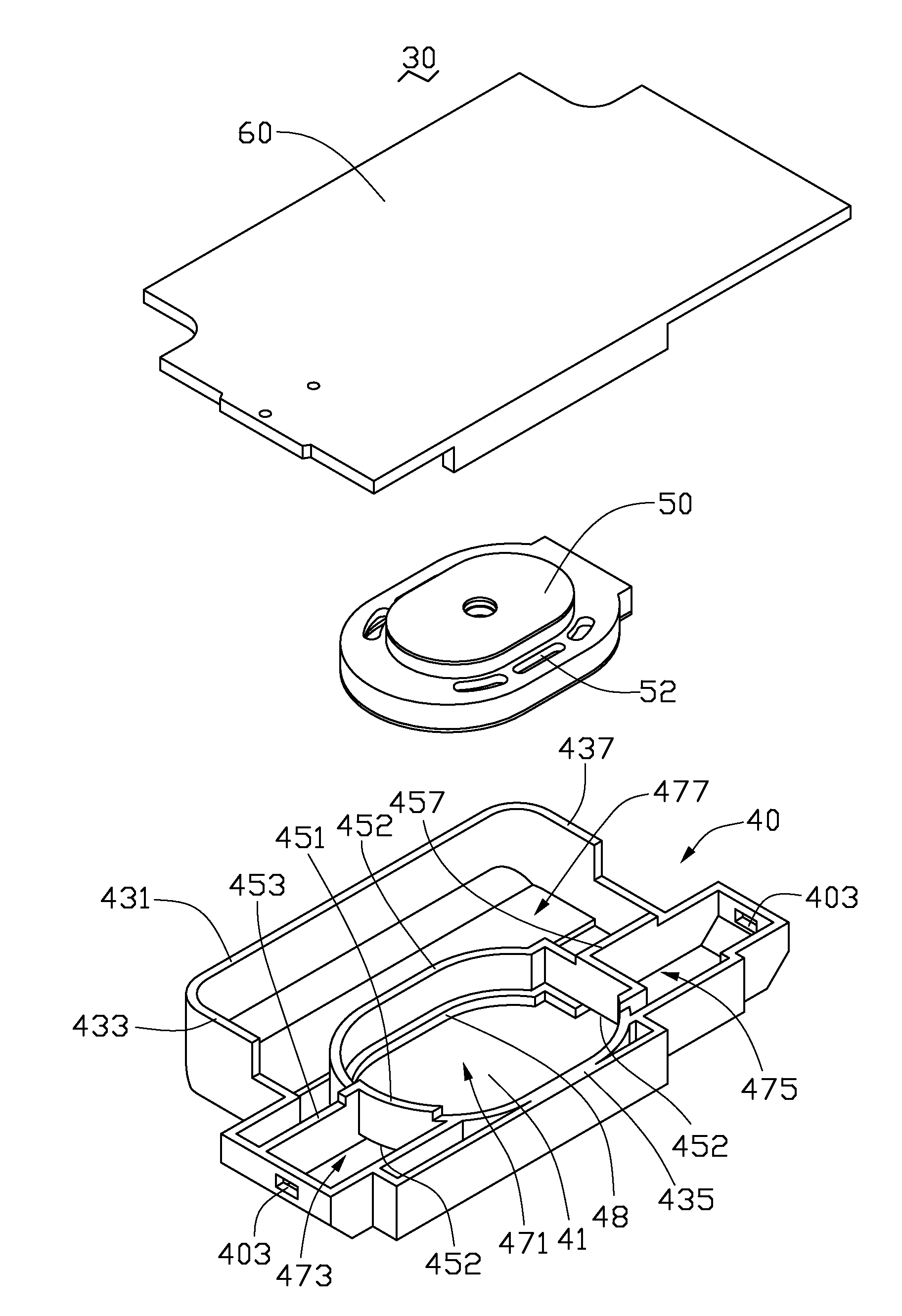
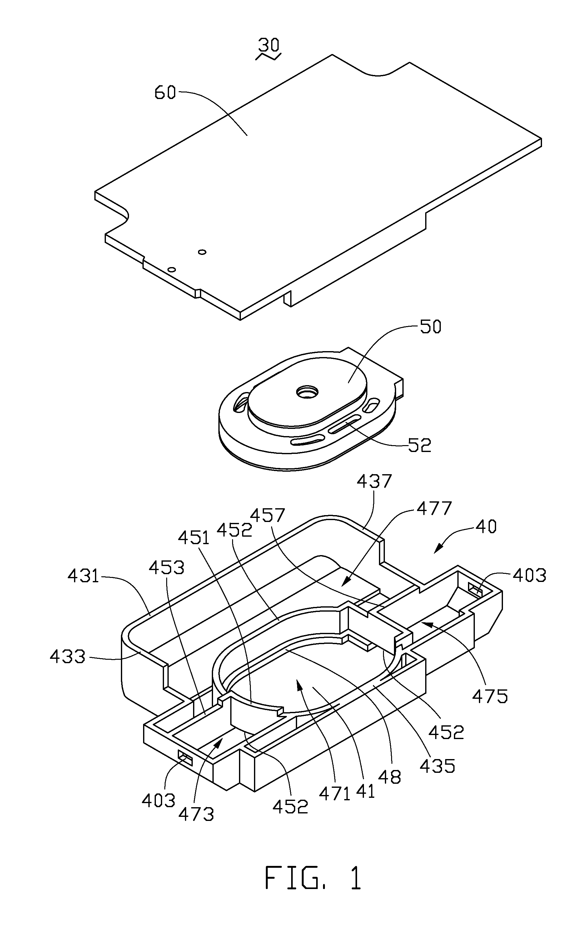
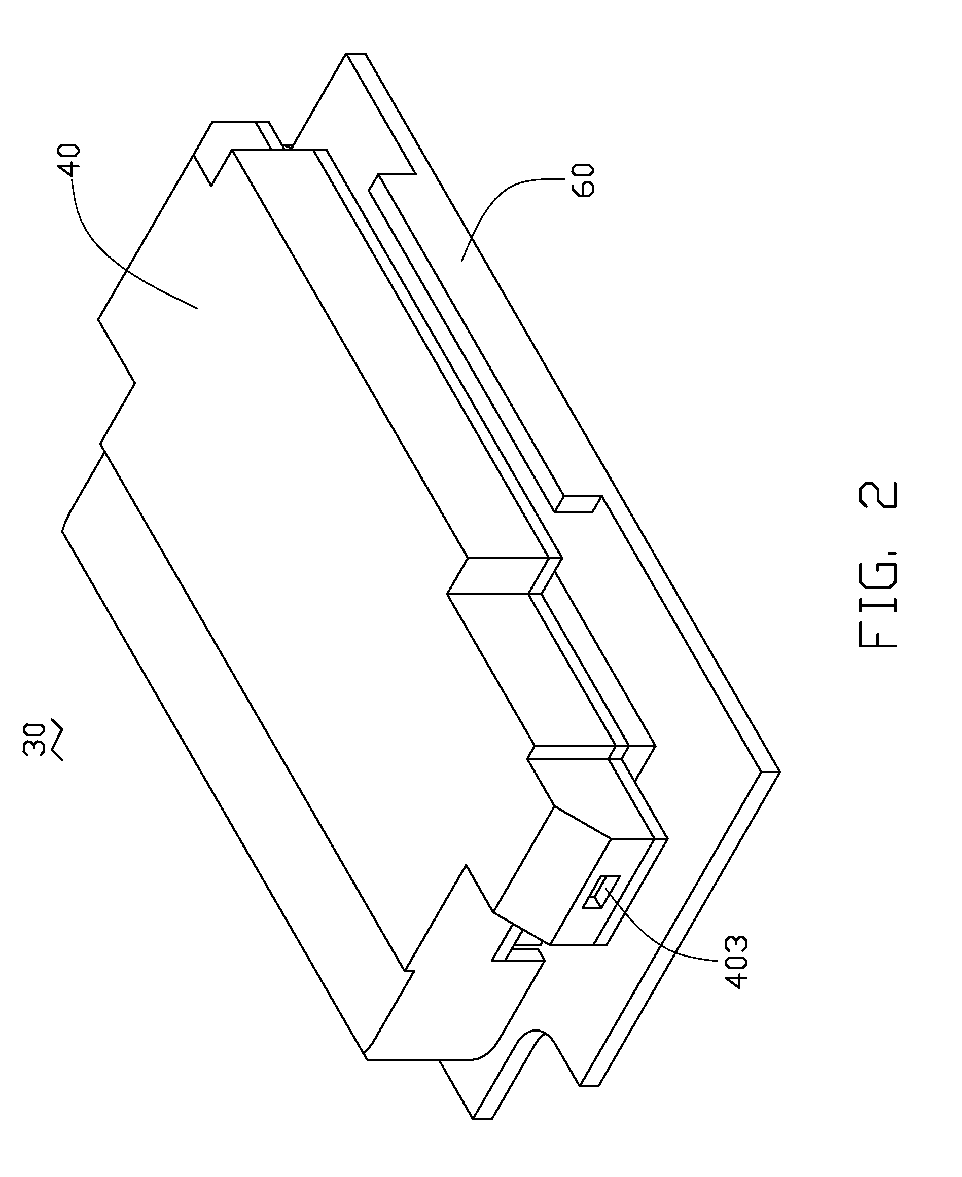
[0014]The present speaker set is particularly suitable for portable electronic devices, such as mobile phones, PDAs, and the like, but could find other applications in which a speaker set is employed. [0013] Referring to FIG. 1, a speaker set 30 according to an exemplary embodiment includes a hollow shell 40, a loudspeaker 50 accommodated in the shell 40, and a back cover 60 mounted on the hollow shell 40 to package the loudspeaker 50 between the shell 40 and the back cover 60.

[0015]The shell 40 is preferably made of anti-vibration material, to prevent the shell 40 resonating with the loudspeaker 50, thereby improving the quality of sound of the speaker set 30. The shell 40 is open on one side, and includes a base wall 41, a plurality of sidewalls, a plurality of partition walls, and a supporting member 48. The sidewalls extend approximately perpendicularly from an outer periphery of the base wall 41. The partition walls extend perpendicularly and from a middle portion of the base w...


PUM


Abstract

A speaker set configured for a portable electronic device includes a hollow shell, a back cover, and a loudspeaker sandwiched between the shell of the back cover. The shell includes a first chamber, a second chamber, a third chamber and a fourth chamber. The second and third chambers are positioned at opposite sides of the first chamber, and communicate with a surrounding environment at opposite sides of the shell. The loudspeaker is accommodated in the first chamber, and divides the first chamber into a front sub-chamber and a rear sub-chamber. The front sub-chamber communicates with the second and the third chambers thereby forming a front resonance chamber. The rear sub-chamber communicates with the fourth chamber thereby forming a rear resonance chamber. Sound waves generated from the loudspeaker are transmitted to and resonate in the front and rear resonance chambers and then transmitted to the surrounding environment in opposite directions.

Description

BACKGROUND[0001]1. Technical field[0002]The present invention relates generally to speaker sets for portable electronic devices, and more particularly to a speaker set which gives a portable electronic device incorporating a speaker set of compact size and good sound quality.[0003]2. Description of the Related Art[0004]Portable electronic devices, such as mobile phones, CD players, MP3 players, personal digital assistants (PDAs) and the like, have decreased both in size and weight over the past few years and are becoming ever more popular with travelers. This demand for smaller size with ever-increasing capability has required tremendous efforts to continually shrink many of the components contained within the device.[0005]In another aspect, portable electronic devices being designed today require multi-media features and provide the user with the same enjoyable experience as that experienced with conventional high quality desktop systems. Thus, the sounds emanating from a portable ...

Claims


Application Information

Patent Timeline
Patent Type & Authority Applications(United States)
IPC IPC(8): H04R1/02
CPCH04R1/021H04M1/03H04R1/2888H04R1/2842
Inventor YANG, TSUNG-LUNGLI, PEI-RONGZHAO, WEN-YUNDENG, XING-XIONG
Owner SHENZHEN FUTAIHONG PRECISION IND CO LTD
Why Eureka
Try Eureka