Image Forming Apparatus

a technology of forming apparatus and forming chamber, which is applied in the direction of electrographic process apparatus, instruments, optics, etc., can solve the problems of disadvantaged apparatus in view of environmental load and economic efficiency, and achieve the effect of accurately positioning and fixing, and avoiding unnecessary replacement of corresponding exposure units

Active Publication Date: 2009-07-30
BROTHER KOGYO KK
View PDF5 Cites 83 Cited by
  • Summary
  • Abstract
  • Description
  • Claims
  • Application Information

AI Technical Summary

Benefits of technology

[0009]In an image forming apparatus configured as described above, each exposure unit when moving from its retreating position to its exposure position is guided to the exposure position proximate to a corresponding photoconductor, along a pair of guide slots formed in the pair of side plates of the support frame which extends in a direction perpendicular to the main direction, and is positioned at the positioning portion of each guide slot. The positioning portion of each guide slot is formed in the corresponding side plate of the support frame which supports the cartridges (photoconductors), and thus the exposure unit can be precisely positioned relative to the corresponding photoconductor at least in the subordinate direction and securely fixed in place. Moreover, with the inventive configuration implemented as described above, the operations of pulling out the support frame from the casing of the apparatus and moving any or each of the exposure units to the retreating position enable the detachment and attachment (i.e., replacement) of the corresponding cartridge(s) (photoconductor(s)) to be carried out independent of the corresponding exposure unit(s), so that when a photoconductor is to be replaced, unnecessary replacement of the corresponding exposure unit can be avoided.
[0010]According to the specific embodiments of the present invention, each of the plurality of exposure units is positioned by the positioning portion of each of the corresponding guide slots formed in the pair of side plates of the support frame, and thus the exposure units can be accurately positioned and fixed relative to the corresponding photoconductors. In addition, replacement of an exposure unit that may not necessarily be required even when a corresponding photoconductor is to be replaced can be dispensed with as the case may be; therefore, the disadvantages in view of the environmental load and economical efficiency, etc. can be overcome.

Problems solved by technology

In such a construction for fixedly locating each of exposure units relative to the associated photoconductor as described above, each of the exposure units may be fixed precisely in an appropriate position relative to the associated photoconductor, but any photoconductor in need of replacement should be removed and replaced together with the associated exposure unit which could possibly not yet need replacing, and thus the apparatus would be disadvantaged in view of the environmental load and economical efficiency.

Method used


Image

  • Image Forming Apparatus
  • Image Forming Apparatus
  • Image Forming Apparatus

Examples


Embodiment Construction

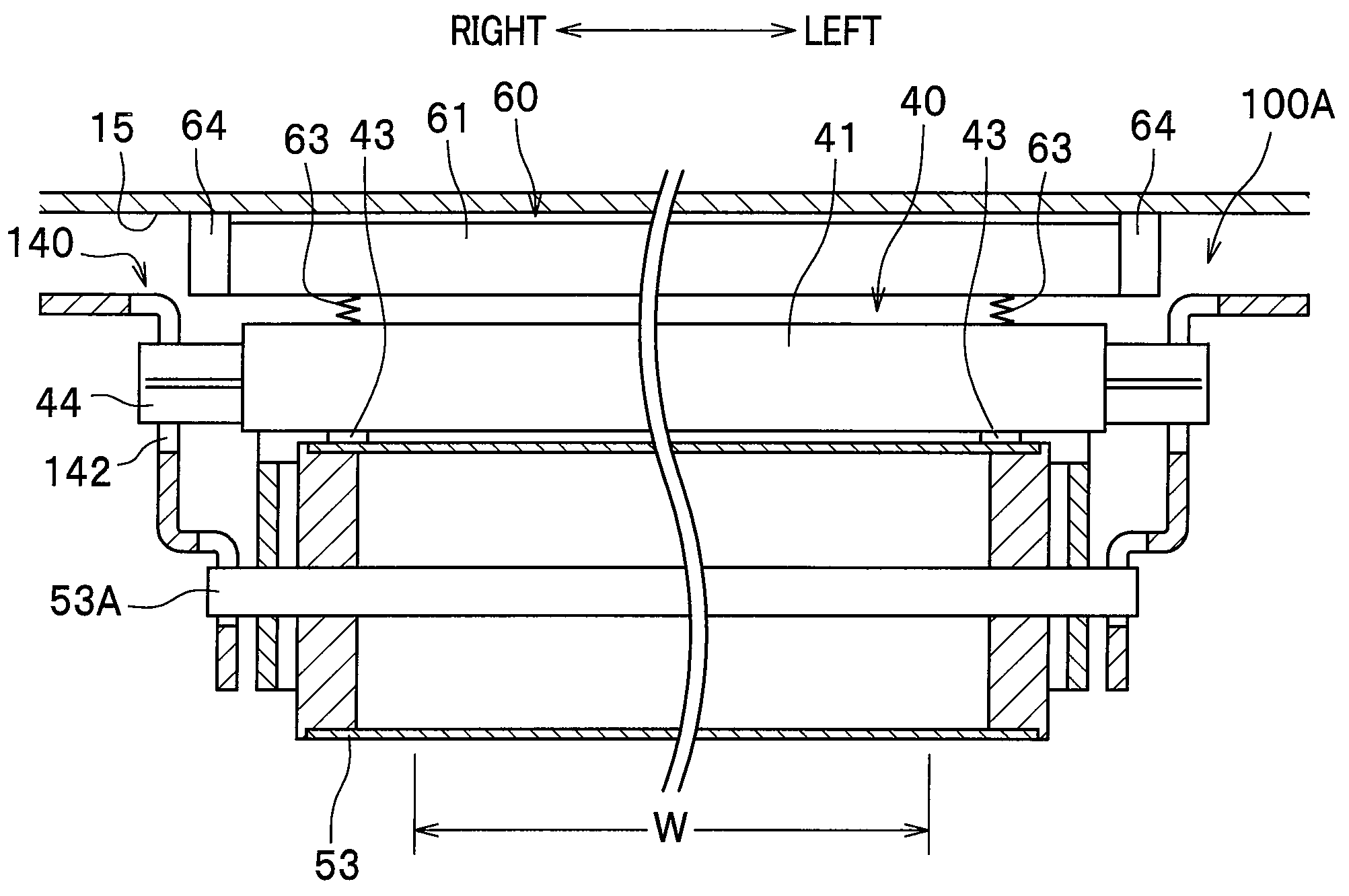
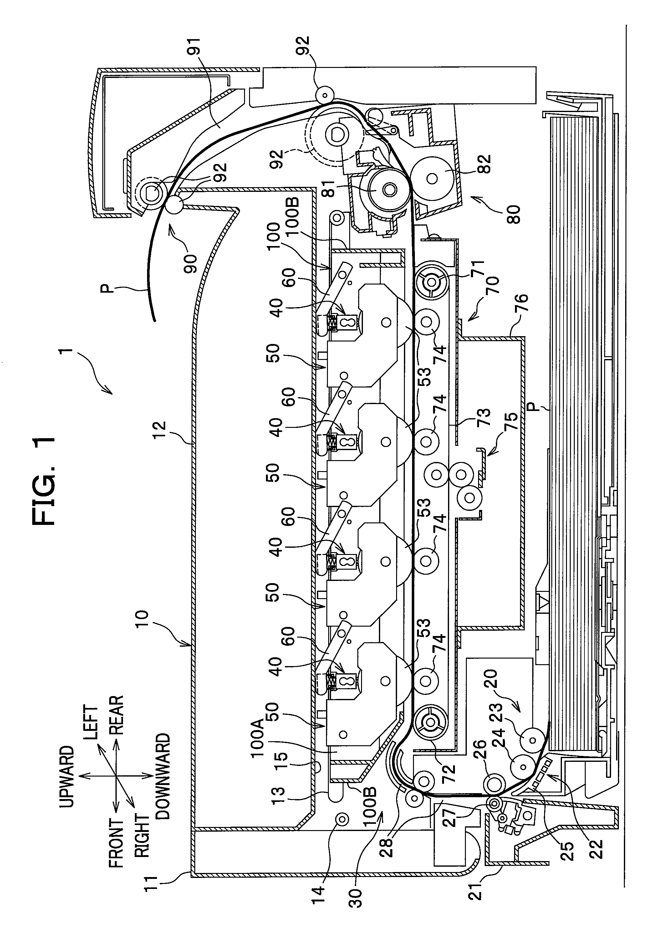
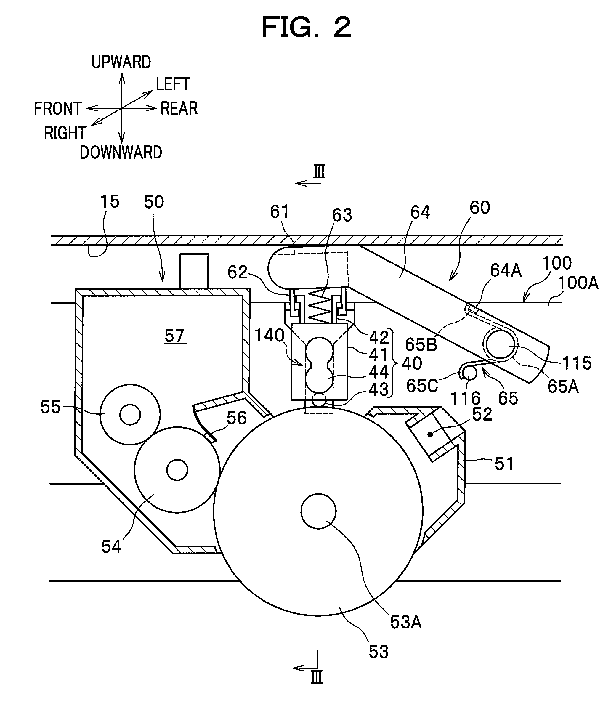
[0022]A detailed description will be given of exemplary embodiments of the present invention with reference to the drawings. In the following description, the direction is designated as from the viewpoint of a user who is using (operating) a color printer. To be more specific, in FIG. 1, the left side of the drawing sheet corresponds to the “front side” of the printer (image forming apparatus), and the right side of the drawing sheet corresponds to the “rear side” of the printer; the back side of the drawing sheet corresponds to the “left side” of the printer, and the front side of the drawing sheet corresponds to the “right side” of the printer. Similarly, the direction of a line extending from top to bottom of the drawing sheet corresponds to the “vertical direction” of the printer.

[0023]As shown in FIG. 1, a color printer 1 comprises a body casing 10 which makes up a housing of a main body of the printer 1. The main body housed within the body casing 10 principally includes a she...


PUM


Abstract

In an image forming apparatus, a support frame configured to support a plurality of cartridges each including a photoconductor is allowed to be pulled out from a casing of the apparatus. A plurality of light-emitting parts configured to expose a corresponding photoconductor to light are arranged in each exposure unit which is movable between an exposure position proximate to the corresponding photoconductor and a retreating position away from the photoconductor. A pair of side plates of the support frame, which extends in a direction perpendicular to a main direction in which the light-emitting parts are arranged, has guide slots formed therein, each of which is configured to guide movement of a corresponding exposure unit between its exposure and retreating positions. Each guide slot includes a positioning portion configured to position the exposure unit in position in a subordinate direction perpendicular to the main direction and to an exposure direction.

Description

CROSS-REFERENCE TO RELATED APPLICATION(S)[0001]This application claims the foreign priority benefit under Title 35, United States Code, §119 (a)-(d), of Japanese Patent Application No. 2008-013715 filed on Jan. 24, 2008 in the Japan Patent Office, the disclosure of which is herein incorporated by reference in its entirety.BACKGROUND OF THE INVENTION[0002]1. Field of the Invention[0003]The present invention relates to an image forming apparatus which includes photoconductors and exposure units, each exposure unit in use being disposed in proximity to a corresponding photoconductor.[0004]2. Description of Related Art[0005]Image forming apparatuses of a type are hitherto known in the art in which a plurality of photoconductors and a plurality of exposure units (e.g., LED heads) are provided such that each exposure unit is disposed in proximity to a corresponding photoconductor so as to expose the photoconductor to light. In this type of the image forming apparatuses, it is desirable to...

Claims


Application Information

Patent Timeline
Patent Type & Authority Applications(United States)
IPC IPC(8): G03G15/00
CPCG03G21/1853G03G2221/1636G03G2221/1684G03G15/04054G03G21/1623G03G21/1647G03G21/1666G03G2221/1687
Inventor OKABE, YASUSHI
Owner BROTHER KOGYO KK
Why Eureka
Try Eureka