
Antenna for an implantable medical device

a medical device and an implantable technology, applied in electrotherapy, therapy, etc., can solve the problems of limiting the situations in which telemetry can take place, inconvenience for clinicians, etc., and achieve the effect of facilitating communication, not complicating the implantation procedure, and resisting breakage or deformation

Inactive Publication Date: 2009-07-30
CARDIAC PACEMAKERS INC
View PDF101 Cites 27 Cited by
  • Summary
  • Abstract
  • Description
  • Claims
  • Application Information

AI Technical Summary

Benefits of technology

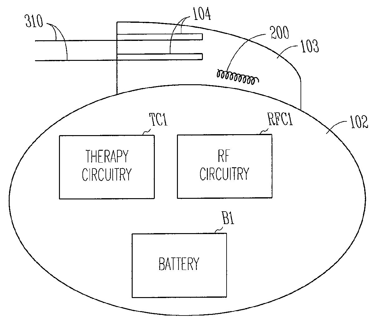
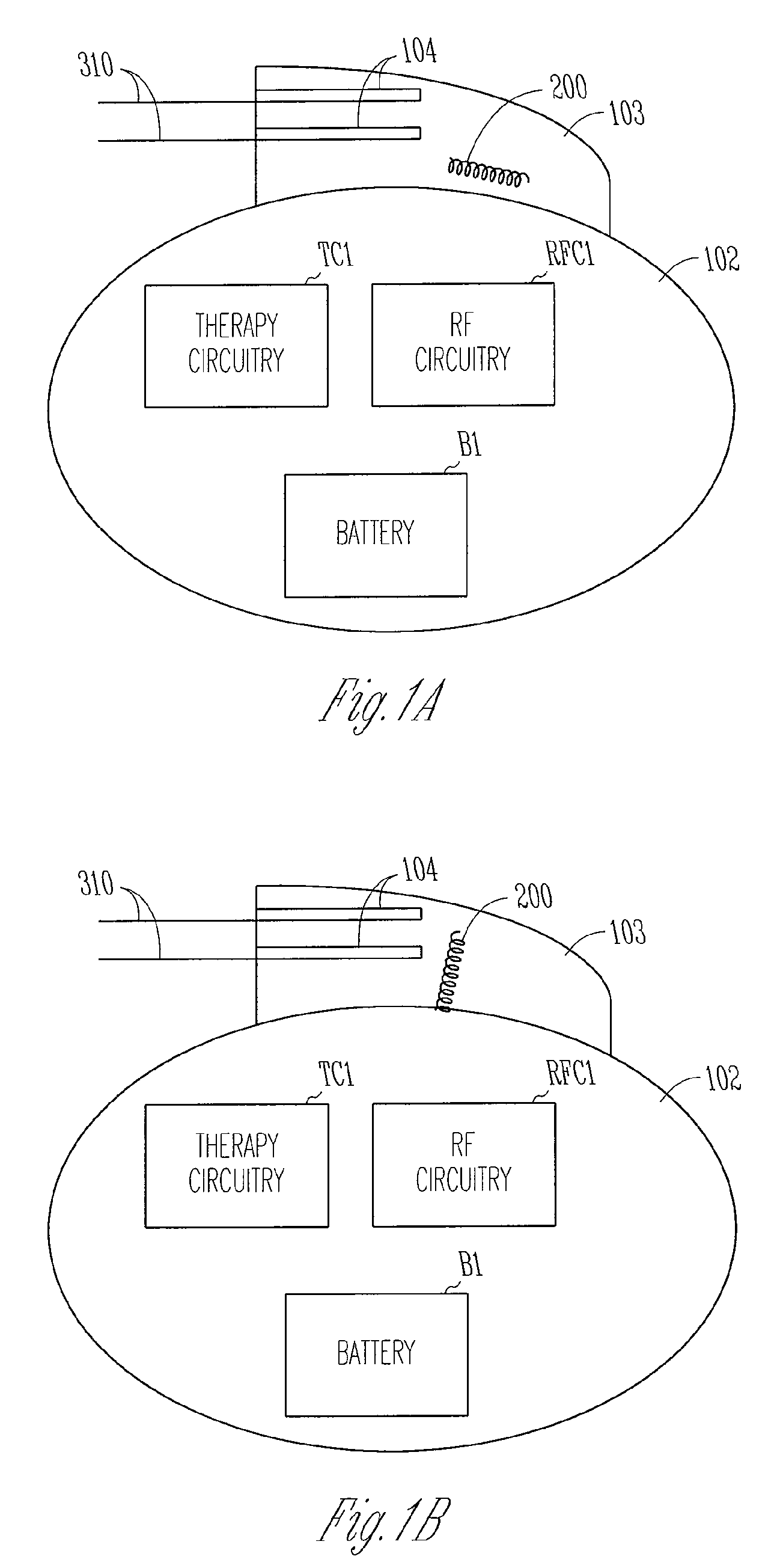
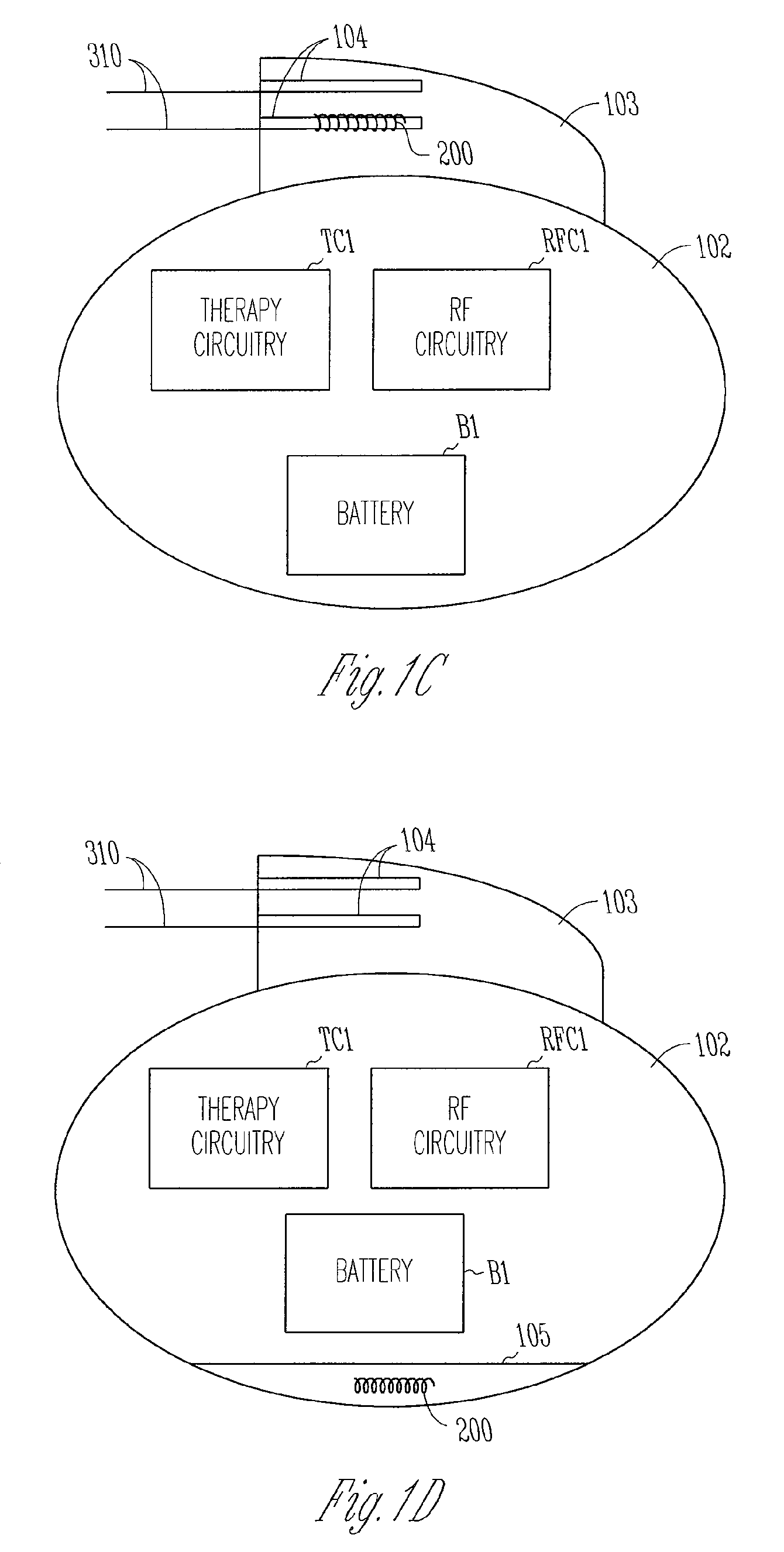
The present invention is about an apparatus and method for communicating with an implantable medical device using far-field electromagnetic radiation. The invention provides an antenna structure that is embedded in dielectric material and located within the unshielded header or housing of the device. The antenna is protected from bending or breakage and requires no special implantation procedure. The dimensions of the antenna structure are constrained by the size of the device and it is desirable for implantable medical devices to be as small as possible. The invention also employs a helically wound dipole or monopole antenna that has a longer effective electrical length than a similarly dimensioned straight wire dipole or monopole antenna. The antenna may also be tuned with a tuning circuit that optimizes its impedance for a particular frequency. The technical effects of the invention are improved communication with implantable medical devices and simplified implantation procedures.

Problems solved by technology

This requirement is an inconvenience for a clinician and limits the situations in which telemetry can take place.

Method used


Image

  • Antenna for an implantable medical device
  • Antenna for an implantable medical device
  • Antenna for an implantable medical device

Examples


Embodiment Construction

[0012]As noted above, conventional radio-frequency (RF) telemetry systems used for implantable medical devices such as cardiac pacemakers utilize inductive coupling between the antennas of the implantable device and an external programmer in order to transmit and receive RF signals. Because the induction field produced by a transmitting antenna falls off rapidly with distance, such systems require close proximity between the implantable device and a wand antenna of the external programmer in order to work properly, usually on the order of a few inches. The present invention, on the other hand, is an apparatus and method for enabling telemetry with an implantable medical device utilizing far-field radiation. Communication using far-field radiation can take place over much greater distances which makes it more convenient to use an external programmer. Also, the increased communication range makes possible other applications of the telemetry system such as remote monitoring of patients...


PUM


Abstract

An apparatus and method for enabling far-field radio-frequency communications with an implantable medical device in which an antenna is embedded within a dielectric compartment of the device. A helical antenna may be employed to save space while still permitting far-field telemetry over a desired range of frequencies.

Description

CROSS-REFERENCE TO RELATED APPLICATION(S)[0001]This application is a continuation of U.S. patent application Ser. No. 10 / 800,596, filed on Mar. 15, 2004, which is a continuation of U.S. patent application Ser. No. 09 / 798,249, filed on Mar. 2, 2001, now issued as U.S. Pat. No. 6,708,065, the specifications of which are incorporated herein by reference.FIELD OF THE INVENTION[0002]This invention pertains to implantable medical devices such as cardiac pacemakers and implantable cardioverter / defibrillators. In particular, the invention relates to an apparatus and method for enabling radio-frequency telemetry in such devices.BACKGROUND[0003]Implantable medical devices, including cardiac rhythm management devices such as pacemakers and implantable cardioverter / defibrillators, typically have the capability to communicate data with a device called an external programmer via a radio-frequency telemetry link. A clinician may use such an external programmer to program the operating parameters o...

Claims


Application Information

Patent Timeline
Patent Type & Authority Applications(United States)
IPC IPC(8): A61N1/08A61N1/372
CPCA61N1/37223A61N1/3727A61N1/37229
Inventor VON ARX, JEFFREY A.MASS, WILLIAM R.MAZAR, SCOTT T.AMUNDSON, MARK D.
Owner CARDIAC PACEMAKERS INC
Learn More