
Graphical user interface for large-scale, multi-user, multi-touch systems

a multi-touch, multi-user technology, applied in the direction of mechanical pattern conversion, instruments, computing, etc., can solve the problems of inability to assign certain interface elements, inability to translate well to large displays and multi-user environments, and inability to effectively use screen real estate in large-scale displays

Active Publication Date: 2009-07-30
MICROSOFT TECH LICENSING LLC
View PDF15 Cites 103 Cited by
  • Summary
  • Abstract
  • Description
  • Claims
  • Application Information

AI Technical Summary

Benefits of technology

[0035]As a further aspect of this embodiment, the invoking step comprises displaying the control element on the display device at a position that corresponds to a position of the generated first stroke.
[0036]As an additional aspect of this embodiment, the invoking step comprises moving the displayed control element to positions corresponding to positions of the generated first stroke during movement of the first moving pointer element.
[0037]Various other objects, advantages and features of the present invention will become readily apparent to those of ordinary skill in the art, and the novel features will be particularly pointed out in the appended claims.

Problems solved by technology

Unfortunately, traditional graphical user interface practices (both desktop window management and application user interface (UI)) do not translate well to or are otherwise ill-suited for large displays and multi-user environments.
For large-scale, multi-user computing environments, it is impractical to assign certain interface elements, such as a “Start” button, to a corner of the screen or a horizontal (or vertical) menu to the edges of the screen, as is common practice on desktop systems, because those areas of the display can be out-of-reach.
Simply making these types of buttons or menus larger or present in many locations on a large-scale display represents ineffective use of screen real estate.

Method used


Image

  • Graphical user interface for large-scale, multi-user, multi-touch systems
  • Graphical user interface for large-scale, multi-user, multi-touch systems
  • Graphical user interface for large-scale, multi-user, multi-touch systems

Examples


Embodiment Construction

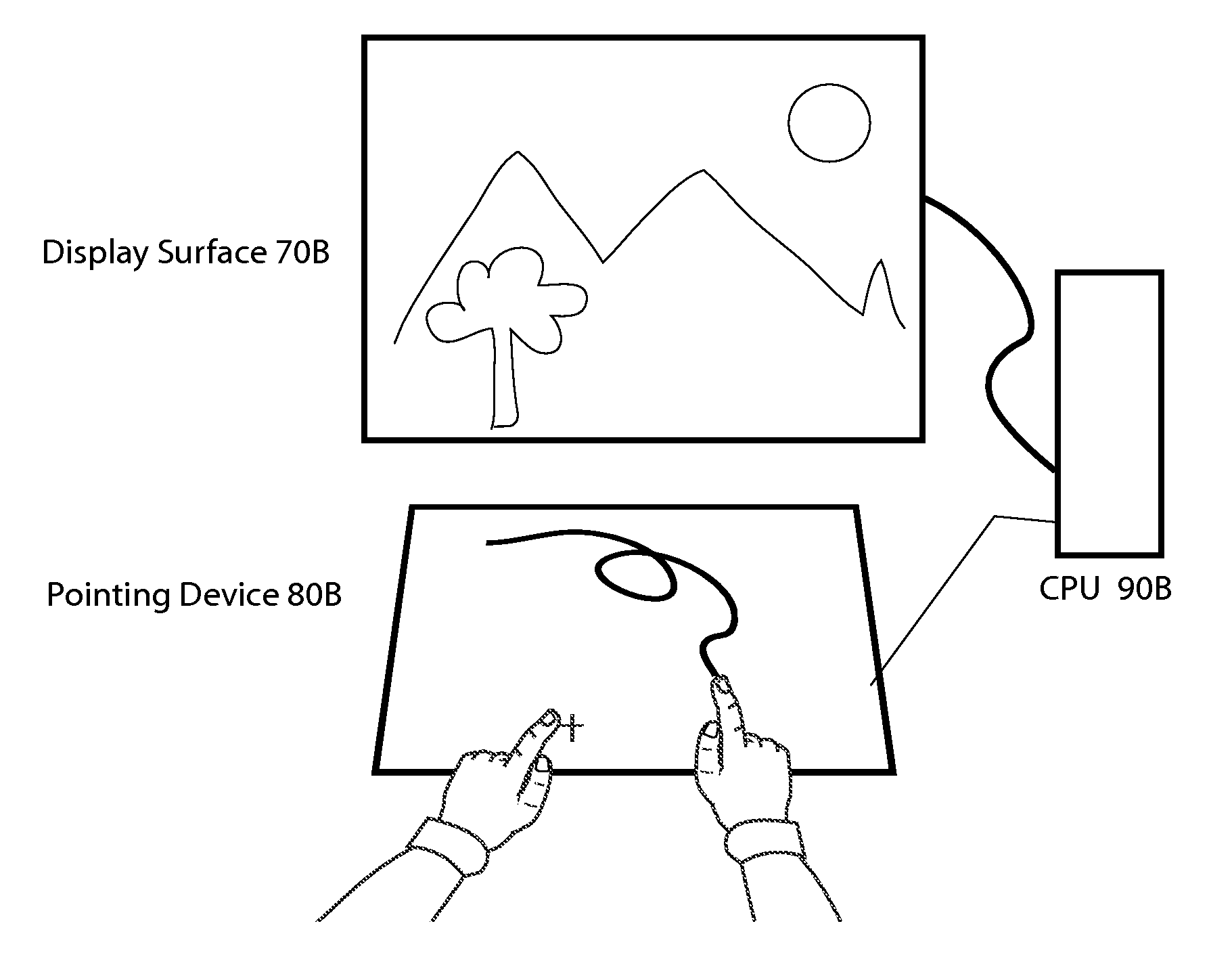
[0045]The present invention pertains to graphical user interfaces that are particularly well-suited for large-scale digital display systems and multi-user interface technologies, particularly multi-touch systems. In such large-scale systems, it is common for two or more users to work side-by-side at the same display and, often, in different application environments. As mentioned above, placing “buttons” or horizontal or vertical menus along the top, bottom or sides of the display represents an ineffective graphical user interface for such large-scale and / or multi-user setting. Even dividing the display into separate “user areas” and providing buttons or menus along the edges of each user area represents ineffective use of space and terribly limits the flexibility otherwise afforded by large-scale / multi-user systems.

[0046]The present invention is described in connection with use of a multi-input or multi-touch device or display. However, it is appreciated that certain embodiments and...


PUM


Abstract

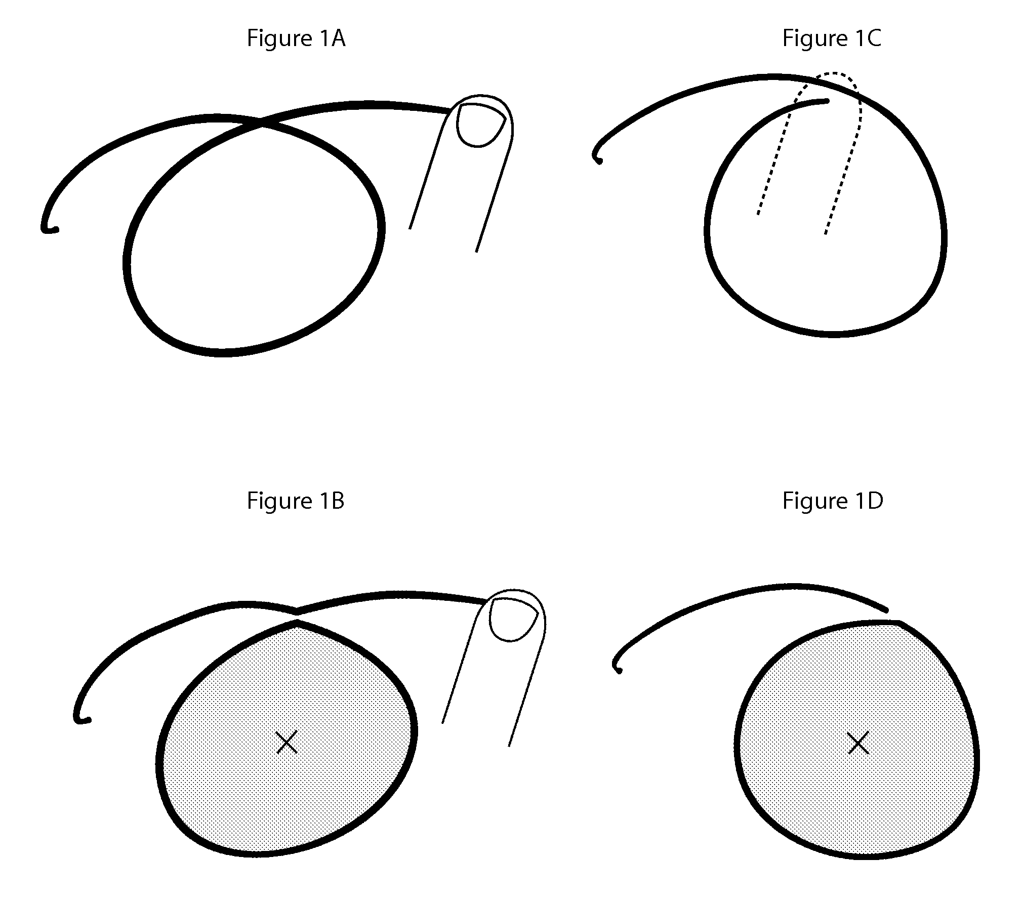
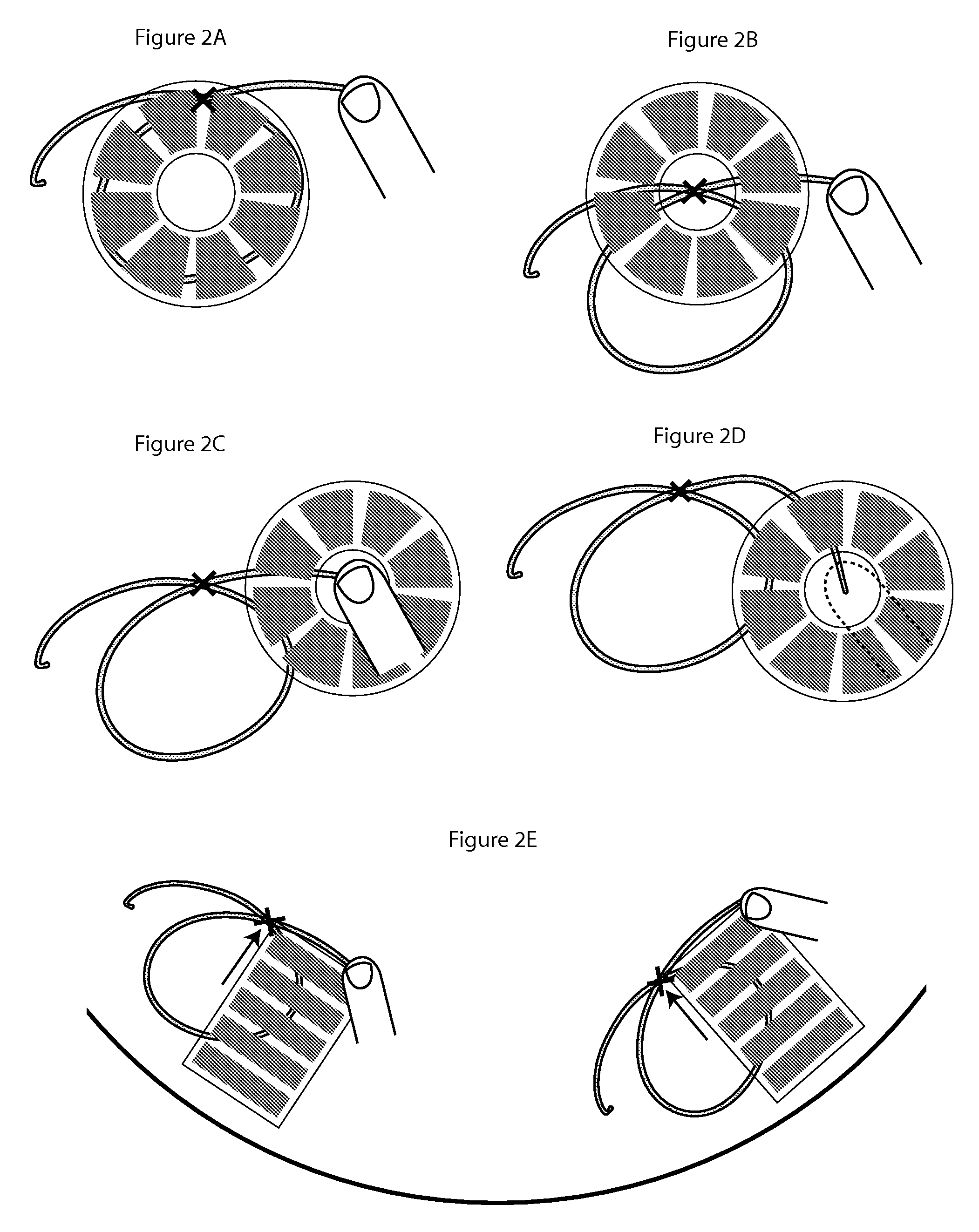
A method implemented on the graphical user interface device to invoke an independent, user-localized menu in an application environment, by making a predetermined gesture with a pointing device on an arbitrary part of a display screen or surface, especially when applied in a multi-touch, multi-user environment, and in environments where multiple concurrent pointing devices are present. As an example, the user may trace out a closed loop of a specific size that invokes a default system menu at any location on the surface, even when a second user may be operating a different portion of the system elsewhere on the same surface. As an additional aspect of the invention, the method allows the user to smoothly transition between the menu-invocation and menu control.

Description

REFERENCE TO RELATED APPLICATION[0001]This application claims priority to U.S. Provisional Patent Application No. 60 / 952,679, filed Jul. 30, 2007, the disclosure of which is incorporated herein by reference.BACKGROUND OF THE INVENTION[0002]1. Field of the Invention[0003]The present invention pertains to a graphical user interface (GUI) for a multi-touch system, and is particularly well suited in a large scale, multi-user setting.[0004]2. Description of the Related Art[0005]Large-scale digital display systems and multi-user interface technologies, particularly multi-touch systems, create a practical environment for rich collaborative workspaces, in which two or more users may work side-by-side at the same display. Unfortunately, traditional graphical user interface practices (both desktop window management and application user interface (UI)) do not translate well to or are otherwise ill-suited for large displays and multi-user environments.[0006]For large-scale, multi-user computing...

Claims


Application Information

Patent Timeline
Patent Type & Authority Applications(United States)
IPC IPC(8): G06F3/01
CPCG06F3/0482G06F2203/04808G06F3/04883
Inventor DAVIDSON, PHILIP L.
Owner MICROSOFT TECH LICENSING LLC
Learn More